This thread has been locked.

If you have a related question, please click the "Ask a related question" button in the top right corner. The newly created question will be automatically linked to this question.

ADC128D818: Measurement error

Part Number: ADC128D818
Other Parts Discussed in Thread: ADS1115

Hi Team,

Our customer noticed that the measurement reading of the ADC128D818 in their prototype board is much higher that the computed value based on the formula in the datasheet. 

There is a difference of around 0.4V between the measured voltage at the ADC input and the calculated value. 

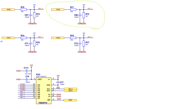
They are using Mode 1, input AIN2 (IN5), internal and external reference voltage and there is always around 0.4V from 0V to ~1.5V. Above ~1.5V the difference became bigger.

They are measuring the voltage at the test point M4. For example, the voltage at M4 is 1.0V and the ADC says 1.4V.

They are using the equation Vin=(Dout*3.3)/4095.

Vin from calculation vs Vin from a FLUKE115 is 0.24V higher at 0V input, and 0.4V higher at 2.6V input.
They also used another multimeter but the results remain the same. 
Please see the schematic diagram below.
What could be the caused of this error?
Regards,
Danilo
  • Hello Danilo,

    I will first point out that the Total Unadjusted Error for the device can start from 3.3mV  (0.1 % of Full Scale). 

    The error you are seeing may be due to the performance of the device. Note that as the code (or input voltage) is greater, the TUE also increases (consider the values as plus and minus).

    If you share the input signal circuit, I can review for improvements. You can also implement calibration coefficient in your calculations to take into account this error. 

    If your system needs a higher performing device, I can help find a better fit.


    Regards

    Cynthia

  • Hello Cynthia, I'm the costumer that Danilo mentioned.

    We had tested the ADC using a digital power supply and measuring the input with the FLUKE115, there's just 0.001V difference in the measuring between the power supply isolated from IN5, and connected to IN5.

    When we started to compare the reading at the FLUKE115 and do the math in our I2C reader, we went from 0 to 2.5V using steps of 50mV.

    Then we noticed that the error is huge, we're expecting up tp 30mV but we are getting up to 400mV, and for our application is useless due we are reading a temperature sensor in a DC motor, the motor has built inside a KTY84-30 temperature sensor, we need to read the temperature in real time, but with that 0.2-0.4V difference in our readings its not possible to have accuracy.

    Thanks in advance for your help.

    Jose.

  • Hello Jose, 

    Apologies for the delay in responding. To make sure I understand correctly. you used a known input from a power supply, and stepped the input signal across the input range. At lower voltage, below 2.5V, there was no error in ADC measurement, but once above this voltage, the error in ADC measurement was seen to reach up to 0.4V. 

    Taking a second look at your schematic, it looks like there are two ground nets, AGND and GND. The input uses AGND, while the ADC is connected to GND. It is recommended to use the same ground for the analog input and the ADC. It is possible that the grounds are split but then connected together, but this connection would need to be near the ADC.

    Regards

    Cynthia

  • Hello Cynthia, thanks for your reply.

    there is always an error, at 0V (grounding the input pin), the output is 0.2V, so at that starting point the error is 200mV; when we reach 2.5V the error goes up to 400mV. The ground that we are using is the same because there is a star ground close to the adc. The resistor doesn’t matter due we are comparing the voltage in the adc’s input pin and the digital output using I2C reading.

    By the way, we get a ADS1115 two days ago and it works perfect at the first try, the error is around 10mV and remains constant along the input range from 0 to 3.3V, we used the same set up that we used with the ADC128D818.

    Thanks in advance for your help.

    Jose.

  • Jose, 

    The error when grounding the input is very suspicious. The datasheet states that when doing single ended measurements, the external source should use the same ground as the ADC.

    Would you connect the voltage source ground to the ground of the ADC and not through the AGND connected ground. I realize that there is a star ground, but  don't really know the location correlation, thus there could be enough leakage to cause the error. 

    Overall, this is not normal behavior for the part, may I ask where you obtained these parts?

    Regards

    Cynthia

  • Hello Cynthia, it’s the same, same ground, we avoided AGND and connected everything with GND. We used the ADS1115 exactly with the same setup and worked perfect.

    cheers.