Hi,
I am not seeing any output when using 81416EVM. Below are details about my setup.
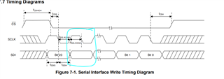
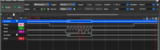
I am using SPI on Arduino Due to update DAC voltages.
Please help.
Connections:
Arduino DUE SPI Pin 3 -> 81416EVM J8.8
Arduino DUE SPI Pin 4 -> 81416EVM J8.4
Arduino DUE 13 -> 81416EVM J8.2
Arduino DUE GND -> 81416EVM J1.31
J7.7 - 15V
J7.6 - GND
J7.5 - 5V
J7.4 - 3.3V
J7.3 - GND
J10: 2-3
Arduino IDE Code:
#include <SPI.h>
int CSdac =13; //Pin on Arduino connected to DAC on tuning board
void setup() {
SPI.beginTransaction(SPISettings(10000000, MSBFIRST, SPI_MODE1));
analogReadResolution(12);
SPI.begin(CSdac);
Serial.begin(115200);
pinMode(CSdac, OUTPUT);
digitalWrite(CSdac, HIGH);
}
void loop() {
Serial.println("Start");
// Set range 0-5V
digitalWrite(CSdac, LOW);
SPI.transfer(0x0A);
SPI.transfer(0x00);
SPI.transfer(0x00);
digitalWrite(CSdac, HIGH);
// Set range 0-5V
digitalWrite(CSdac, LOW);
SPI.transfer(0x0B);
SPI.transfer(0x00);
SPI.transfer(0x00);
digitalWrite(CSdac, HIGH);
// Set range 0-5V
digitalWrite(CSdac, LOW);
SPI.transfer(0x0C);
SPI.transfer(0x00);
SPI.transfer(0x00);
digitalWrite(CSdac, HIGH);
// Set range 0-5V
digitalWrite(CSdac, LOW);
SPI.transfer(0x0D);
SPI.transfer(0x00);
SPI.transfer(0x00);
digitalWrite(CSdac, HIGH);
// Power up device
digitalWrite(CSdac, LOW);
SPI.transfer(0x03);
SPI.transfer(0x0A);
SPI.transfer(0x84);
digitalWrite(CSdac, HIGH);
// Power up all channels
digitalWrite(CSdac, LOW);
SPI.transfer(0x09);
SPI.transfer(0x00);
SPI.transfer(0x00);
digitalWrite(CSdac, HIGH);
// Enable broadcast all channels
digitalWrite(CSdac, LOW);
SPI.transfer(0x05);
SPI.transfer(0xFF);
SPI.transfer(0xFF);
digitalWrite(CSdac, HIGH);
// Write code to all channels
digitalWrite(CSdac, LOW);
SPI.transfer(0x0F);
SPI.transfer(0xFF);
SPI.transfer(0xFF);
digitalWrite(CSdac, HIGH);
delay(100000000);
}