This thread has been locked.

If you have a related question, please click the "Ask a related question" button in the top right corner. The newly created question will be automatically linked to this question.

ADS125H02EVM

Other Parts Discussed in Thread: ADS125H02EVM

Hello,

I would need your help on how to connect a load cell in the evaluation board ADS125H02EVM.  I have a 6wire load cell and I want to connect it in the board- Excitation (+) with AVdd, Excitation (-)->GND, Sense(+)-Ref+

Sense(-)-Ref(-), Out(+)->?, out(-)-? Could you please help me understand with which pins I should connect them?

Kind regards,

Androniki

  • Hi Androniki Diakou,

    SIGNAL+ and SIGNAL- would connect to AIN0 and AIN1, respectively (I believe you referred to these as OUT+ and OUT-)

    SENSE+ and SENSE- connect to REFP0 and REFN0 (or REFP1 and REFN1), respectively

    EXC+ and EXC- connect to AVDD and GND, respectively

    Please note that the absolute voltage on the reference inputs (REFPx and REFNx) is limited to AVDD+0.05V, so if you apply an excitation voltage >5V, you will need to attenuate this signal before applying it to the reference pins.

    The analog input pins (AINx) have no such restriction, and can support input signals up to +/-2.5V from the the high voltage supplies (HVDD and HVSS)

    -Bryan

  • Hello Bryan,

    Thanks for the clarification. I cannot see where is the AVdd connector pin in the board. Is it possible to help me find it out or indicated in the board layout?

    Kind regards,

    Androniki

  • Hi Androniki Diakou,

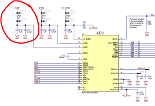
    There are test points on the ADS125H02EVM (TP12 and TP13) that can be used to connect to the AVDD voltage. You will need to solder in header pins or wires here however, since these are effectively just larger vias.

    I would suggest reviewing the ADS125H02EVM user's guide for more information: https://www.ti.com/lit/pdf/sbau318


    -Bryan

  • Hello Bryan,

    I connected the- Ecx+ to AVDD and the - to ground. I read the manual but I am not that sure if I am configuring fine the device because I cannot see through the app the output for the different forces applied to the load cell. I have done the following configuration: I have set the refN1 and Refp1 as input and then I sent high. Is that correct? Could you let me know what additional steps I should take see the data?

    Kind regards,

    Androniki

  • Hi Androniki Diakou,

    The first thing you should do is input a known voltage into the ADC and make sure it is functioning properly. This will also get you familiar with the ADC EVM GUI. I would apply a 1V signal from a clean source and make sure the ADC can convert this input properly.

    Also note that the default settings on the GUI set the ADC data rate to 20 SPS and collect 2048 samples. This will take several minutes, so if you are hitting "Collect data" and it appears nothing is happening, this could be the issue. I would make sure to set the data rate and the number of samples appropriately.

    If you are having any other issues taking data, please be very specific as to what you are doing and how the GUI / EVM is responding.

    -Bryan