This thread has been locked.

If you have a related question, please click the "Ask a related question" button in the top right corner. The newly created question will be automatically linked to this question.

AMC1106M05: several question for AMC1106M05

Part Number: AMC1106M05
Other Parts Discussed in Thread: AMC1305M05, AMC1305M25

Hi Team

Let me ask short question

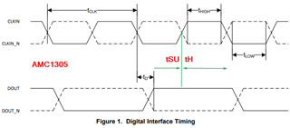
a).Does AMC1106M05 have a Duty cycle clock limitation for external clock?(Ex:+/-10%)

b).The differential input resistance is 4.9 kΩ, but is it necessary to calculate the current value considering the combined resistance with the detection shunt R? (Combined resistance including input filter)

C) Do you have a recommended input filter for analog input?

best regards

TATSU

  • Hi Tatsu,

    • Yes!  The AMC1106 has duty cycle limitations!  Please see tLOW and tHIGH in section 7.10 and let us know where you might have issues with the specification. 
    • Yes!  The input resistance would be in parallel with the 'shunt'.  In current monitoring applications this is usually not a system issue since the shunt resistor values are normally very small (milli or micro ohm range).  For voltage sensing applications, it can be a concern since the 'shunt' in that case is relatively large (100's or 1000's ohms)
    • Filter will be application specific in most cases, but 10 ohm and 10nF capacitors are where we start with most applications..
  • Hi Tom san

     Thank you for your quick response.

    And, could you let me know the ansewer for follwing query from customer?

    I understand that I sholdn't write about AMC1305 in this thread, if posible could you answer?

    a). Does AMC1305 have a DOUT hold time like AMC1106? I seaech it on  section 7.11 datasheet. but I  can't find. 

    b).The tD of the AMC1106 is specified from the rising edge of the clock, but is it specified from the falling edge of the AMC1306?

    c).Do you have any idea to limitate the  input current?

    best regards

    TATSU

  • Hi Tatsu,

    For the AMC1305, you would need to use the rising edge of the clock to strobe valid data into your digital filter module.  From 7.11, tD is 0 min and 15nS MAX, so the hold time is a little different in this device.  You would need to take tD MAX and subtract that from the low CLKIN to see the setup time provided to the digital filter module.  The hold time would be the entire high time of CLKIN in this case.

    The AMC1106 and AMC1306 both have the same timings and they are different from the AMC1305 in that the AMCxx06 devices change data on DOUT with the rising clock edge.  The AMC1305 changes DOUT with the falling clock edge.

  • Hi Tom

     Could you let me know the answer for following  questinog?

    • Does AMC1305M have a rising up/fall down time limitation of DOUT?
    • Although the analog input signals (AINP and AINN) have a limit of 10 mA input current,what kind of considerations are necessary for use within the input current range?

    best regards

    TATSU

  • Hi TATSU,

    There are no specific limitations on the output rise/fall time from the standpoint of the AMC1305Mxx DOUT driver.  I'm not sure that I understand your second question.  The AMC1305M05 and AMC1305M25 have input voltage limitations of 50mV and 250mV respectively.  These input voltages are normally derived by passing current through a shunt resistor.  There is no limitation on the current flowing through the shunt, its the shunt size that limits the voltage seen by the AMC inputs that is the main concern.  

  • Hi Tom san

    Let me ask about  AMC1305M05DWR and AMC1106M05DWVR.( sorry for asking the AMC1305 in this thread)

    1)Regarding Rind

     =>I found the typical value on detasheet( AMC1305M05DWR5kΩ, AMC1106M05DWVR4.9kΩ),, but do these devises have Min and Max value?

    best regards

    TATSU

  • Hi TATSU,

    If you look at the functional block diagram (section 8.2) in the datasheets, you should notice two sets of two resistors around a differential amplifier that connect to the analog inputs.  These resistors are what form Rind.  They are matched to ensure the gain stays within the MAX limits stated in the Electrical Characteristics section of the datasheet.  The value of Rind can vary by approximately +/-10% on a lot-to-lot basis.

  • Hi Tom 

    Thank you for your response.

    But I couldn't understand that "They are matched to ensure the gain stays within the MAX limits stated in the Electrical Characteristics section of the datasheet."

    Could you explain again?

    best regards

    TATSU

  • Hi Tom 

    Let me ask additinal question.

    How to calculate the Gain drift when tempeature will change? (temp range:0-80℃)

    best regards

    TATSU

  • Sure,

    From the datasheet: "The AMC1106 incorporates front-end circuitry that contains a differential amplifier and sampling stage, followed by a ΔΣ modulator. The gain of the differential amplifier is set by internal precision resistors to a factor of 20 with a differential input resistance of 4.9 kΩ." 

    You asked about the 4.9k ohm tolerance, it can vary slightly, but the 'factor of 20' remains constant so that the gain stays within the datasheet limits.  For gain drift, look at Figure 14 in the AMC1106 datasheet along with the gain drift spec.  The typical number is +/-20ppm/`C, so over 80 degrees you are looking at 1600ppm or 0.16% overall.