Other Parts Discussed in Thread: LMK04828
Hi Team,
(1) Does CLK2/CLK2C accept LVDS? Or is LVPECL only available?
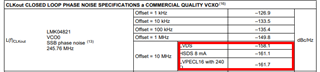
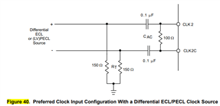
(2) For LVPECL, I want to confirm how to set the clock interface. Per datasheet, it looks :
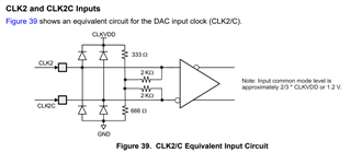
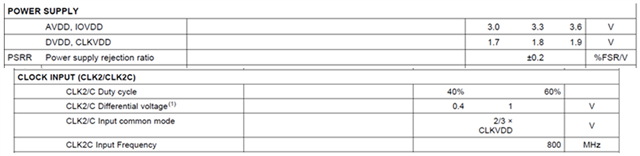
- VCM = CLKVDD 1.8V * 2/3 = 1.2V
- 1V swing
- supply voltage should be 3.3V domain
Is it correct?
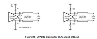
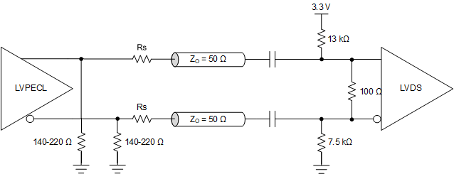
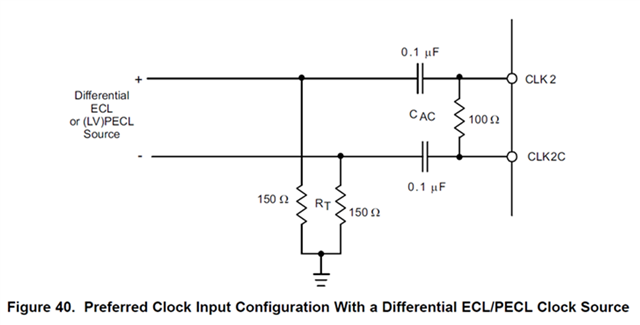
Is the circuit configuration correct?
Sincerely,
Ella