This thread has been locked.

If you have a related question, please click the "Ask a related question" button in the top right corner. The newly created question will be automatically linked to this question.

ADS1298R: What's the difference between the DC/AC leadoff detection?

Part Number: ADS1298R
Other Parts Discussed in Thread: ADS1298

Hi,

    The ADS1298R datasheet tells that I can choose DC/AC leadoff detection.

    And the DC detection has a) Pull-Up/Pull-Down Resistors b) Current Source methods.

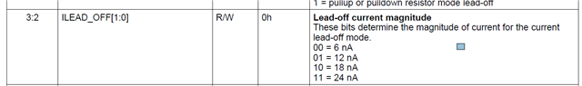
    And the Current Source has ILEAD_OFF registers to set the current magnitude.

    My Question is, what should I concern when I choose the LeadOff method?

    I think the input impedance is as larger as possible, isn't it? So the current source is the best choise, isn't it? If it is, what value should I set to ILEAD_OFF?

    Thank you.

Frank

  • Hi,

    "    My Question is, what should I concern when I choose the LeadOff method?"

    Comments: this could be very broad and generic questions, and it depends on the need at any time moment.

    Maybe take a look of datasheet  9.3.1.7.4 Lead-Off Detection-

    here are some concepts and examples to think depending on what your applications and products need -

    DC method in either pull-up/pull-down resistor or current method, can be used to detect electrode On or Off, but not "contact strength".

    AC method can be used to detect contact strength(designers&developers algorithms required), but it may introduce some high frequency interference, that may need to be taken care of.

    ---------------------------------------------

    All above require developers&designers to do experiements&tests&data collection&analysis&play with all the associated current magnitude(e.g. ILEAD_OFF) and threshold settings with respect the using RLD or not, electrodes, skin conditions, product designs, etc, and reiterate the processes before making decisions.

    -------------------------

    Do you have/use an evaluation kit/board(EVM)?

    It's recommended to use EVM and test with an ECG simulator, and do experiements&tests&data collection&analysis&play with all the associated current magnitude(e.g. ILEAD_OFF) and threshold settings with respect the using RLD or not, etc, and reiterate the processes to get familiar and understand before making decisions, and then move on to the product prototyping and reiterate above with electrodes, skin conditions, product designs.

    --------------------------------------------------------------------------------

    Thanks

  • Hi ChienChun Yang,


         I prefer to use the DC method, it's much eaiser to use.

         According to the datasheet 9.3.1.7.4, DC methods:  

             a) Pull-Up/Pull-Down Resistors      with 10MO input resistance.

             b) Current Source methods.           with 100MO input resistance.

         What else is the difference?    I think the input impedance is as larger as possible, isn't it?

         So, why a) is also a choice? In what situation, a) is better than b)?

         Yes, I have an evaluation kit/board(EVM) and have tested with an ECG simulator. And I see no difference between a) and b).

          Best Regards,

    Frank

  • And also,

          I didn't find any information from the datasheet 9.3.1.7.4, what will the Lead-off current magnitude effect?


  • Hi,

    For, "I think the input impedance is as larger as possible, isn't it?"

    datasheet page 40 -"The current source or sink gives larger input impedance compared to the 10-MΩ pullup or pulldown resistor"

    For "why a) is also a choice? In what situation, a) is better than b)?"

    Comments: no definite answers for that it's to give users more options. As least for a) it saves some current. Usually customers decide after they implement and do experiments&tests&data collection&analysis&V&V.

    --------------------------

    not sure what you mean or what you are asking for "      I didn't find any information from the datasheet 9.3.1.7.4, what will the Lead-off current magnitude effect?"

    Usually product developers&designers will need to tune those magnitude with respect to their product designs, patches/electrodes, cables, peripheral circuits on PCBA, etc and then decide threshold accordingly. It affects the sensitivity and threshold setting user want to use ,i.e. that is experiments&tests&data collection&analysis&V&V and tuning process product developers&designers need to do before making decisions.

    Thanks

  • Hi ChienChun Yang,

          Thank you very much.

          You mean the best parameters is related to my application, I should test different paras on my product and get the best paras.

          I am lack of experience at leadoff detection.  Is there any application or technical reference documents that is related with leadoff detection?

          Best Regards,

    Frank


  • Yes, I am glad you ask -

    Some suggestion to start.

    Do you have an ADS1298(R) evaluation kit/board(EVM)?  It's highly recommended to get one.

    Do you have ECG simulator? It's highly recommended to get one.

    One you get the two above, you may start experiments&tests&evaluation by following the ADS1298EVM user guide with ECG simulator first to acquire ECG signal as well as test the lead off detection.

    And, make sure you do some study for the Right Leg Drive(RLD) and test&compare when use it and without it.

    Start with above to get familiar with&study the device and most of the register settings. Suggest to change registers settings one-by-one or little-by-little and make observation&notes&table&comparison, etc.

    After certain level of understanding from above, you may move on to design your own PCBA and use some real electrodes for repeat and/or further experiments&tests data collection/analysis and then tuning the parameters, e.g. current magnitude and the detection threshold.

    Thanks,

    Chien