This thread has been locked.

If you have a related question, please click the "Ask a related question" button in the top right corner. The newly created question will be automatically linked to this question.

DAC7760: Occasional SPI Failure: DAC7760 reads an extra 0 bit between address byte and first data byte

Part Number: DAC7760
Other Parts Discussed in Thread: DAC8760EVM, DAC8760

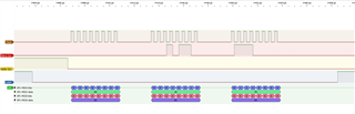
Our DAC7760 is sometimes reading an extra zero bit between the address byte and the first data byte. It doesn't happen all the time, but when it does, the problem will persist until a power cycle or perhaps a reset. I don't know yet what causes it or how to reliably avoid it. Here are three consecutive logic analyzer traces.

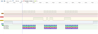
  1. Write DATA register with value 0x2CF0
  2. Write read command for DATA register
  3. Read DATA register as 0x1670 which is 0x2CF0 shifted one bit to the right

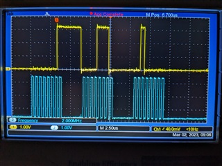
I have lots of traces like this. It's also not limited to the DATA register. I first saw the problem with the GAIN and ZERO registers. I'm running the SPI clock at 2MHz. I've verified the logic analyzer traces on a scope.
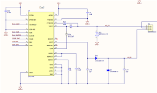
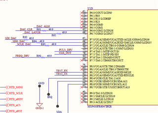
Our schematic:

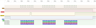
A write to DATA of 0E20. It was read back as 0710.

  • I think the DAC7760 returns the user calibrated value when you read the DATA register. I don't see this documented. The closest hint is a mention under Programmable Slew Rate: "If the DAC data register is read while the DAC output is still changing, the instantaneous value is read."

    Update Gain:  1.20  b353
    #### registers before gain update
    DAC  Ctl: 1001  Cfg: 0320  Gain: 8000  Zero: 0000  Status: 0000  Data: 0ff0
    #### registers after gain update
    DAC  Ctl: 1001  Cfg: 0320  Gain: b350  Zero: 0000  Status: 0000  Data: 1320
    DAC DATA write failure 0ff0 ==> 1320
    DAC DATA write failure 0ff0 ==> 1320
    ...

    0x0ff = 255
    255 * 1.2 = 306
    306 = 0x132

    Also, the data sheet doesn't mention that gain and zero offset unlike the DATA register are 16 bit values with the least significant nibble masked. Notice that a written gain of 0xB353 results in a gain register of 0xB350. I guess that internally, it's all 16-bit, and that DATA is really a 16-bit number with a size 16 step between values on the DAC7760 resulting in an effective range of 12 bits.

  • I think the "extra inserted" zero bit is the default gain, 0.5, applied to data values. A divide by 2 is a right shift of one bit.

    • Gain is a 16-bit unsigned number where 0x0000 = 0.5x and 0xFFFF = 1.5x. The least significant 4 bits are zeros.
    • Zero is a 12-bit signed number stored in the most significant 12 bits of a 16-bit register.
    • Data
      • WRITE: the desired, un-calibrated setting
      • READ:
        • the current value if slewing
        • if slewing disabled, the calibrated setting, i.e. setting * gain + zero
        • the value after calibration cannot exceed the register range
          • you can't make the bottom of the range go lower with a negative offset
          • so, an offset of 0.1 will output Range_Min + 0.1
          • but, an offset of -0.1 will read Range_Min because Range_Min + (-0.1) is below Range_Min
          • a negative offset will apply for larger values, though
          • all of the above is empirical from testing
  • Hi Harvey,

    Joe will review this and respond on Monday.

    Thanks,

    Paul

  • Harvey,


    I had to go and test this for myself and you are correct. The read of the DAC data register will report back the DAC data after it has been updated with the gain and zero calibration registers, or it will report the instantaneous value when the device is slew-enabled. I tested this with the DAC8760EVM which does have the capability to write and read back the registers in the front frame. I also went to the design documents and found that this was the intended design, so not having it the datasheet is an oversight. Sorry about the confusion.

    I put together a block diagram and this is what the path looks like (without the slew enable drawn):

    Does this answer your original question where the read is intermittently wrong, or is this the source of your problem?


    Joseph Wu

  • Thanks for the confirmation. I found it helpful to describe the calibration parameters like this:

    • zero: signed 12-bit (shifted 4 bits left in a 16-bit register)
      • -2048...2047
    • gain: unsigned 16-bit (least significant 4 bits masked) mapped to 0.5...1.5
      • 0...65535 in steps of 16

    Related, follow-up question:

    In 4-20mA mode, how does one correct for the chip falling short of the endpoints?

    Example1:

    • Gain=1.0, Zero=0.0, CODE_OUT=0
    • Chip reads 4.01mA. So, we want to apply a negative zero offset, but it has no effect because after the math, the number is clamped to a CODE_OUT of 0...4095. So, 0 - Offset is still 0.

    Example2:

    • Gain=1.0, Zero=0.0, CODE_OUT=FFF  (12-bit 7760 values)
    • Chip reads 19.85mA. So, we want to boost the gain, but it's the same situation as before. FFF * 1.x is still FFF.

    How do I solve for this?

  • Harvey,


    I don't think there are any easy ways to correct for the value at the endpoints. The calibration in the DAC8760/DAC7760 is a digital calibration. The output at the DAC is adjusted based on modifying the DAC code, and not by adding or subtracting the current (or voltage) at the output.

    One way to get the exact range would be to set the output range to 0-24mA. In this range, you could adjust the gain and offset so that you get exactly 4-20mA for the range. There may be some slight INL errors because of the interpolation from the digital calibration, but they should be < 1 LSB. You could also do the same thing with the DAC8760 with higher resolution, so that these errors are even smaller.


    Joseph Wu

  • Harvey,

    Incidentally, Setting the mode to 0-24mA and then setting both the Gain and Zero offset calibration codes to 0x2AAB should set the range to 4-20mA. These values should set the gain to about 0.6667, and the offset to 4.000 mA.

    Joseph Wu 

  • Thanks, that's the conclusion I reached as well. I'll ask if its more important to have resolution or accurate endpoints.