This thread has been locked.

If you have a related question, please click the "Ask a related question" button in the top right corner. The newly created question will be automatically linked to this question.

LM98725: How to design ?

Part Number: LM98725
Other Parts Discussed in Thread: DS90CR218A

Hi all,

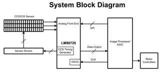
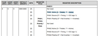
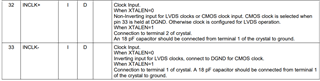
I want to use LM98725 for CIS sensor.

Can LM98725 be used for CIS Sensor?

I want to use STM32H723xx. (MCU)

I want to use LM98725 via PSSI pin (MCU function).
I don't know that How is interface?
Do I connect the data output from lm98725 to the MCU pin through ds90cr218a?
Can you tell me how to connect the LM98725 to the MCU? 
  • Hello shshin,

    Thank you for your interests in the LM98725. We will look into this inquiry. Please expect a response by 3/31.

    Best regards,

    Bill Chieng

  • Hi Bill Chieng. I will wait for your reply. Please help me

  • Hello shshin,

    I believe you reached out to TI support regarding this part. You will receive a follow up with a more detailed response. Regarding your questions above:

    Do I connect the data output from lm98725 to the MCU pin through ds90cr218a?
    • According to the application circuit, yes the LM98725 data outputs are feed into the DS90CR218A. A receiver that deserializes the LVDS which converts the datastream into 21 bits of CMOS/TTL output.
    Can you tell me how to connect the LM98725 to the MCU? 
    • This is dependent on your system needs. With that said, following the application circuit, the output of the LM98725 is feed into a deserializer, which can be fed into an MCU.

  • Hi Bill Chieng. 

    Can you tell me your email? 

    Can you review or Confirm the circuit I designed?

    The output of LM98725 from DOUT0 to DOUT7 is connected with DS90CR218A input.
    However, is it right to connect the output of DS90CR218A to the MCU?
    And 21Bit, should I connect all 21Bit to MCU? I don't quite understand this part.

    I don't know how the output of DS90CR218 comes out. Why 21bit?

  • Hi Bill Chieng 

    I have one more question.

    I use CIS, not CCD.

    Then can I use NC for PHIA1,2 PHIB1,2 PHIC1,2?

  • Hello shshin, I am not familiar with the DS90CR218A. I would suggest reaching out and creating a new post for DS90CR218A to answer your concerns regarding that part (DS90CR218A).

    Another output format, the LM98725 also offer CMOS output format (must be configured accordingly). Can you refer to “4.23 CMOS Output Format” to determine if this what you are expecting for your MCU input (in your case: PSSI pin)

    I've sent a private message to you with my email contact.

    Although, I want to inform you that system-level support for this device is limited. Support is limited to what is provided in the datasheet.

    Regarding your follow up thread:

    Please refer to datasheet “4.15.4 Support for CIS Sensors” to determine if your CIS sensor is supported with this device.

    NC for PHIA1,2 PHIB1,2 PHIC1,2?

    Yes, I would advise looking at the register definitions (table 18 in the datasheet) to set the appropriate PHIA1,2 PHIB1,2 PHIC1,2 registers accordingly (for instance, avoid turning those pins active). Based on the register definitions, pins are in Tristate.

    Best regards,

    Bill Chieng

  • Hi Bill Chieng. 

    Thank you for your help. 

    I have more question.

    I'm thinking of using CMOS OUTPUT.

    Then, is it correct to NC the INCLK- and INCLK+ pins?

  • is GND right , not NC?

  • Hello shshin,

    I would refer you to the pin description below:

    This is on page 4 of the datasheet. Set the XTALEN bit accordingly. I would interpret NC as no connection, for the previous question "PHIA1,2 PHIB1,2 PHIC1,2" are okay to ground as long as you configure the register accordingly (setting these pins as tristate).

    Best regards,

    Bill Chieng