This thread has been locked.

If you have a related question, please click the "Ask a related question" button in the top right corner. The newly created question will be automatically linked to this question.

ADS1015-Q1: Quick start Config Failed

Part Number: ADS1015-Q1
Other Parts Discussed in Thread: ADS1015

Hi team,

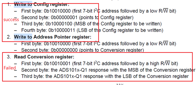
When the customer involved ADS1015-Q1, they found that the read failed in step 3 according to the Quick Start configuration. What is the possible cause?

  • Hi Alan,

    The procedure is correct.  How does the customer know that the action failed?  Is there oscilloscope or logic analyzer screen shots that verify the communication is being sent as expected?  When the micro is requesting a read, it must also provide the necessary clocks to be able to transmit the data.  Also, the last byte received by the micro should be followed by a NACK so that a proper STOP can be transmitted.

    Best regards,

    Bob B

  • Hi Bob,

    Due to my network issues, it is currently not convenient to upload the customer's code.
    Please allow me to describe the customer's issue in text:
    The customer uses ADS1015 to measure the voltage value of the thermistor, and then converts it to DS90UB948 for reading through ADS1015. At present, the customer has found that the value read from the register does not match the theoretical value calculated by the actual voltage value. For example, the thermistor value read is 1.69V, and according to theoretical calculations, the ADC value should be 1048, but the actual reading from 0h of ADS1015 is not.

    Are there any configuration settings or other issues with conversion quantification?

  • Hi Alan,

    I don't really need to see the code, but it would be very helpful to know if the read communication is actually working.  Oscilloscope or logic analyzer shots of the I2C communication would be very helpful.  Does the customer read back the configuration register to verify that the written configuration has been completed correctly?

    It is not clear from your description what the result actually is when 1.69V is applied.  Also, how is the thermistor voltage connected?  The chosen mux selection is AIN0 = AINP and AIN1 = AINN.  The customer needs to make sure that the mux selection actually matches with the input connections to the ADC.

    If the full-scale range (FSR) is +/-2.048V then 1 count (LSB) is equal to 1mV.  This means that the 1.69V should return 1690 counts (0x69A) and not 1048.  The conversion register data would appear as 0110 1001 1010 0000b which is 0x69A left-justified within the 16-bit register.

    One additional thought is that after the configuration write, it takes almost 1ms before the first conversion will complete.  The customer should delay reading the conversion result until after it completes and updates the conversion register.

    Best regards,

    Bob B