Other Parts Discussed in Thread: ADS1014, ADS1013
Hello TI experts,
My customer now designs temp/humidity sensor for car. and they considers ADS1014 for ADC.
The condition is as below;
1. VDD : 5.1V (actual voltage from DCDC)
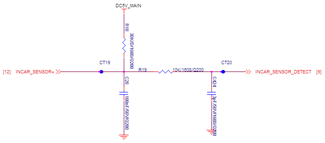
2. Analog voltage : 0V~5.0V
My question is as below;
if the input voltage is almost 5V(analog), would it be convert well to digital value with ADS1014?
if it is not because VDD and input voltage is almost same, Please give me another solution. (i.e. using another device or change the value of VDD, or other solution..)
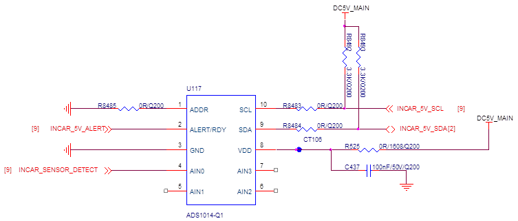
Also please check that it is necessary to insert pull-up resistor between ADS1014 and level shifter.
(the data flow is as follows; (analog data)->(ADS1014)->(I2C 5V to 3.3V level shifter)->(Processor), they already use pullup resistor between level shifter and processor. should we insert pullup resistor between ADS1014 and level shifter additionally?
Please check this issue. Thanks.
Best regards,
Chase