This thread has been locked.

If you have a related question, please click the "Ask a related question" button in the top right corner. The newly created question will be automatically linked to this question.

ADS131M06 Reset Command Operation

Part Number: ADS131M06

Hello,

We have integrated 2 ADS131M06 with AM243x device.

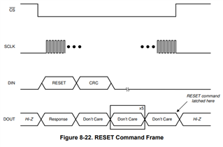
We are trying to reset the ADS131M06 devices by issuing a RESET command, when ADC s go out of sync.

We are however not able to get the ADC back to reading correct values even after initiating the RESET command.

-> Is there a timing requirement on when the RESET command can be given?

Thank you,

Prithvi

  • Hi Prithvi,

    Welcome to our E2E forum. The timing for RESET command is shown below. Can you please read the Reset status bit in STATUS register and the Reset bit in MODE register after initiating a RESET command? can you provide a timing plot for /CS, SCLK, DIN and DOUT? 

    Best regards,

    Dale

  • Thanks Dale for the reply.

    The status register is reading with the Value 0x05FF from ADC1 and ADC2.

    We are observing the issue during ESD Test.

    I am working towards getting the waveforms.

    Are there any implications of trying to reset the ADCs multiple times? 

    Thanks you!

  • Hi Prithvi,

    The RESET status bit in the STATUS register is always 1b by default after the ADC is powered up, so please write 0b to the RESET bit in the MODE register to clear the RESET status bit in the STATUS register before you send the reset command to the ADC and read the STATUS register from the ADC.

    It seems like the ADC was latched during your ESD test. Could a hardware reset  to the /RESET pin recover the ADC back to a normal operation? or have to cycle the power supply to recover it?

    Do you have any diodes on the input and power supply pins to protect the ADC from ESD transient signal?

    Best regards,

    Dale

  • Hi Dale,

    I am doing a the hardware reset ( SYNC/RESET pin pulled low for 1.2ms and then made High ) and setting the WLENGTH to 32 bit - sign extended operation. This is able to get the ADC back to normal operation.

    We observed that after the ESD, DRDY is at 4Khz. Under Normal operation, its observed at 8Khz. We want to detect in FW when this happens and then try to issue the reset sequence automatically. When I try to do this, seems like DRDY is latching (sometimes). 

    Thank you,

    Prithvi

  • The DRDY during ADC normal operation:

    The DRDY Signal when we issue a RESET looks like this

    After ~15ms, THE DRDY recovered back to 8.138kHz.

    But Sometimes we observe that the DRDY does not recover with RESET

  • Hi Prithvi,

    Unfortunately, I do not have a setup so that I am able to reproduce your test and situation. However, ESD test is a system level test. Protecting a system or a device against ESD is largely dependent on pcb layout design, while selecting propter protection components including Schottky or TVS diode is very helpful to suppress ESD transients and avoid latch-up on the device. Please see some application documents below. I would suggest to add the protection to make your system more robust against ESD.

    Circuit for protecting ADS131M0x ADC from electrical overstress

    ESD Protection Layout Guide

    Best regards,

    Dale