This thread has been locked.

If you have a related question, please click the "Ask a related question" button in the top right corner. The newly created question will be automatically linked to this question.

DDC264: INPUT RANGE

Part Number: DDC264
Other Parts Discussed in Thread: DDC118

Hi TI Expert,

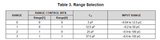
  My client was unable to determine and control the range of input current for some reasons,unless it had been detected and monitored with DDC264.So there will be a problem that the input current might be higher or lower than input range at the Table 3.Range Selection before feedback data  transmit to MCU when they need it for the frist time(it has passed several cycles of CONV transition and Data retrieval) ,then my client will adapt input current according to feedback data.

1/What would happen the input current not in the range(phenomenon)?

2/Will it(higher or lower than input range) make damage to DDC264?

3/what should i do to aovid and prevent the damage occur?

  • 1/What would happen the input current not in the range(phenomenon)?
    Comment: it depends. the readings, results and performance can become unexpected/unpredictable and not guaranteed.
    2/Will it(higher or lower than input range) make damage to DDC264?
    Comments: yes, it's possible if excessive high current. Please follow the absolute maximum rating in data sheet. 7.1 Absolute Maximum Ratings and 7.3 Recommended Operating Conditions

    3/what should i do to avoid and prevent the damage occur?
    Comments. customer should do sufficient experiments and data collection&analysis with their sensors or any kind of input sources first to understand the input range and well controlled & regulated to limit and prevent current outside the datasheet suggested range, and customers could use an input resistor divider, with a resistor to ground (Rp), in parallel with the current source (photodiode or whatever...) and one in series (Rs) into the input of the DDC (between PD and DDC).

    Thanks

  • Hi,

    Just to add... If I got it right, I think the current ranges we are talking about here are within the max ratings, just that they may need for instance to set the 150pC range but they are on the 12.5pC, and by the time they realize, the device may have taken few samples saturated. This shouldn't damage the device. The input integrator will saturate, disabling its capability to keep the input voltage to ground (virtual ground). Hence the input voltage will start shifting up till the input diode protections kick in. If we are talking about <uA type currents, these will be fine. The only thing is that the input will have some voltage, which means that the input parasitic C, is actually holding a given Q (Q=VC). When the input switches to larger range, that charge will flow into the integrator, in the first sample after the switch. Honestly, that transient itself is not clean, so, no big deal. Probably one or two samples later (can't recall if DS says anything about transient gain settings) everything will be normal.

    My recommendation is that one starts with the larger range (150pC) and switch to the lower once the signal level is determined. But again, if during the lower range, a peak comes that exceeds that, then just go through the adjustment and throw away few transient samples.

    Regards,

    Edu

  •   Thanks for your reply.

    I can just find voltage range about analog input,can't find the current range in data sheet.7.1 Absolute Maximum Ratings.

    Mybe i don't describe clearly.

    For example,integration time tINT is 240us and analog input current is 10mA,(240us*10mA= 2'400'000pC>157.5pC) it is out of range,but it won't damage DDC acorrding to Eduardo Bartolome's reply.

    How about the input current? Is it out of range and cause the damage? I don't get it.

  •   So when it out of 'pC' range,it won't damage DDC,just take few samples saturated and get 0xF...(256s) from data feedback, right?

  • Hi,

    It depends on how much "out of pC" range you are referring to?

    157.6 pC is out of range  and 1576 pC and 15760 pC are also out of range.

    Thanks

  • Hi Jieyin,

    10mA is actually quite a lot... Can't really tell what would happen with so much current. I was talking about the case where current is in the uA range (within what the device can handle in a low gain, high FSR, setting) but the device is in a high-gain setting when this uA "large signal" comes. 

    You are right the 264 doesn't give a max current limit. DDC118 (an older device) has a 750uA limit. A while back we discussed something similar for that device and, although the input protections may be fine, there were concerns with mA type currents:

    • If the saturation happens in more than one channel, all those currents will flow together eventually through a common trace somewhere. Usually that common trace is wide enough, though, to deal with this, so, low risk...
    • A more serious concern which could have driven the 750uA limit is that the input traces are designed quite thin to reduce input capacitance. So, there may be a risk of electromigration.

    You can probably assume that 10mA for short period of time will not damage the device but if it is DC for a long period of time, it could eventually. Unfortunately these devices have been released for a while so no way to get more information than this. 

    So, with that said, I can think of couple of options to deal with it but not sure if any will be satisfactory:

    1. Avoid that currents more than few uA stay on for long times. I don't know the system level, but one option is to put a series resistor between the output of the source (point A) and the input of the DDC (point B). As the current increases, the voltage on point A should increase effectively "shutting down" the current source. This works is for instance, it is a PD and point A is one of the biasing points. 
    2. The resistor divider that Chien mentioned is a sure way to protect the device, but the obvious issue is that it attenuates also the smaller currents, reducing the effective sensitivity.

    Regards,
    Edu