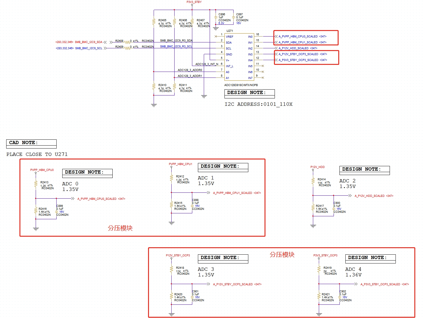
At present, the circuit uses ADC128D818CIMTX/NOPB chip to collect voltage. The schematic diagram and serial port driver reading values are shown in the figure:
Problem description: During normal power supply, the correct voltage value can be collected; However, when the collected voltage is not powered, a high voltage will also be read with a probability of about 50%,
Positioning process:
The normal power supply of IN0 and IN1 PVPP is 2.5v, and when not powered, the voltage collected is 5v, and the drive return value is 2560,
The normal power supply of IN3 is 12v, and when not powered, the voltage collected is 12v, and the drive return value is 2560,
The normal power supply of IN4 is 3v3, and when not powered, the voltage collected is 6v, and the drive return value is 2560
IN5 and IN6 are not connected to any devices, and there will also be small driver return values of 267/268
1. Using an oscilloscope to detect the waveform before and after overvoltage collection, there is no actual voltage present, only minimal external interference, and the collected problem voltage time is completely out of sync, eliminating the possibility of external noise interference causing collection errors.
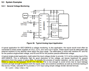
When there is an error in the collected voltage, the drive return values are all 2560. According to the manual, calculate the formula DOUT=[ Δ VIN/VREF] × 2 ^ 12, carried in at 2560, Δ The VIN is 1.6v,
Please help to take a look. We have the problem of voltage collection errors when there is no power supply. What is the reason for the return value error to be the same? Why does this collection error state occur? If there are any other issues or unclear descriptions, please feel free to communicate at any time,