This thread has been locked.

If you have a related question, please click the "Ask a related question" button in the top right corner. The newly created question will be automatically linked to this question.

ADS52J65EVM: Coupling analog input to ADC

Part Number: ADS52J65EVM
Other Parts Discussed in Thread: ADS52J65, THS4509, TINA-TI

Hi Team,

Can you have a look at the following customer inquiry, please?

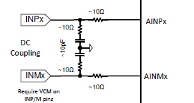
I am using the ADS52J65EVM for evaluating ADS52J65. I would like to DC-couple the Analog input to the ADC. Unfortunately, there is no information available in the ADC-EVM Datasheet on how to achieve this.


 I would like to make the following changes to the Schematic to dc-couple the analog input to the ADC.

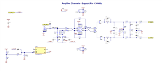
1.       Remove(and Short) the C194, C193, C203.

2.       Optionally, remove(and short)C201, C202. 

Could you please confirm if these changes are enough?

Thank you,

Franz

  • Hi, 

    How does your input waveform look like (DC-operating point, bandwidth, etc.)? You will have to convert this to ADC’s acceptable input range and input common mode. The ADC expects an input common mode of 750mV (on AINPx and AINMx) and can support a differential swing of 2Vpp.

    You will have to make a few of more changes on the board:

    1. Place 0 ohms at C193, C203, C194, C201, C202
    2. Remove R180, R188
    3. Place 10 ohms at R162 and R168
    4. Place 10 ohms at R176, R194
    5. Remove R200, Place 0 ohms at R198
    6. Place 0 ohms at C201, C202;
    7. Use 0V for OPAMP- (J24); place 0 ohms on FB16.

    After this, I also recommend you to perform DC-operating point and transient simulation (TINA-TI or PSPICE) with THS4509 (or whichever Opamp you choose) for your final input network and input waveform. Ensure that common mode on AINPx/AINMx is 750mV and differential swing (AINP – AINM) is within 2Vpp.

    Opamp TINA-TI models are available online (https://www.ti.com/product/THS4509#design-tools-simulation). You can model the ADC using the Analog Input Equivalent Circuit (Figure 61 in datasheet).

    Thanks, 

    Karthik

  • Hi, 

    Thanks a lot for your reply.

     Analog input has 0-2V amplitude and is less than 5MHz Gaussian pulse in our Flow cytometer instruments.

    We have designed an anlog front-end circuit. LTspice simulation results show good results. 

    Thanks for the support. 

    Kind Regards,

    Panneer-Raja Vajravelu

  • Hi Panneer, 

    I will close this thread since we already have a conversation going over email. 

    Thanks, 

    Karthik