Other Parts Discussed in Thread: ADC3683,
We have been using the ADC3683 development board (ADC3683EVM) with the FPGA we have set up to receive data through LVDS from ADC3683. Channel B has not been terminated and is not currently used by the design. Channel A1 has been observed to produce consistent, but incorrect data following an 18-bit constant pattern set.
During debugging, the LVDS lines DA1_P and DA1_N show no shorts to ground or any other LVDS lines. They offer proper connection to the connector at positions E15 and E16. All continuity testing has been done with the 2 boards powered off and connected to one another.
The chip is configured via SPI through the FT4232H onboard, registers reflect their set value during testing. In between tests, the chip is reset with the onboard reset switch, and only 3 registers being the test pattern registers are set to help simplify issues that may appear in other parts of the configuration.
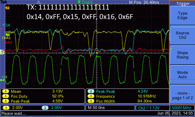
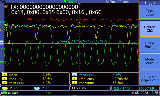
Two tests have been recorded here. The first is where all ones are sent followed by all zeros in the next test. During this channel, A0 reflects the data set in the register but A1 reflects what appears to be 4 bits of the data.
The 2 images provided show the data attempting to be transmitted, the SPI commands used to set the data, and lastly each signal.
This odd behavior of A1 appears consistent with all of our other testing. Further testing or more data about the setup or issue to track down the source of the issue is always welcome. Thank you for your time in helping to sort out this odd behavior.