This thread has been locked.

If you have a related question, please click the "Ask a related question" button in the top right corner. The newly created question will be automatically linked to this question.

Scalling ADS7881 Output

Expert 2370 points
Other Parts Discussed in Thread: ADS7881

Hi Tom,

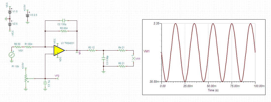
I am trying to scale ADS7881 outout but I couldn't manage to do it. I inputed 1.25 VDC to adjust R25 to mid scale but the code axis keep moving as I move R25. However, I adjusted R25 to set the DC line around 2045 code range. When I switched to sine wave, it was totally out of scope which can be seen in the 1st waveform shown in the figure given below.

http://i52.tinypic.com/2heftko.jpg

After that I adjusted R25 with sine wave, Y-axis shows code length from 0 to 4095, I tried to center the waveform aorund 2048, it has maximum value of 4095 but the waveform doesn't start from 0 which means it is not center around 2048 (0x800). It can be seen in the 2nd waveform given at the same link as above.

Can you please tell me if some thing is wrong ?

Thanks.

  • Hi BAS,

    I work with Tom and can help you with this. Do you have a schematic of the circuitry you are using around the ADS7881? I'm not sure what R25 is referring to.

    Regards,
    Chris

  • Hi Chris,

    Figure 1. ADS7881 Input Buffer Circuit on Page no. 3 of the following document.

    http://focus.ti.com.cn/cn/lit/ug/slau150/slau150.pdf

    After getting the input samples, I am converting them into normal scale as shown below.

    ((float)r_buffer/4095.0f)*vRef

    vRef = 2.5 V

    Waiting for your help.

    Thanks.


  • Hi BAS,

    Thanks for pointing me to the schematic

    So you applied a DC signal of 1.25V to Vin and adjusted R25 so that the output of the amplifier/ADC was at mid-scale or 1.25V. Then when applying the sine wave the output voltage clipped. This behavior is the result of the input sine wave having a DC bias voltage of 0V. Add a 1.25V offset to the sine wave or adjust R25 to reduce the common-mode voltage to 0.625V (you can measure this at test point #4, TP4).

    For the second waveform you showed, what was the voltage at TP4? (I bet it was greater than 0.625V).

    Also, is the peak amplitude of the sine wave 1.25V? (It looks like it might be a little smaller and not taking up the entire full-scale range of the ADC).

    Regards,
    Chris


  • Hi Chris,

    Yes the peak amplitude of the sine wave is exactly 1.25V which is being generated by arbitrary waveform generator. I can't add 1.25V offset to ths sine wave because it will be difficult while working with real world signal. Second option is feasible for me so I adjusted the voltage at TP4 to 0.625V but there is still a minor error of few volts which can be seen from the snapshot.

    http://i51.tinypic.com/71iqko.jpg

    Waiting for your reply.

    Regards,

    BAS


  • Hi BAS,

    What is the min and max code you are reading on the ADS78881? From the graph it looks likes the sine wave is almost covering the full extent of the full scale range. The ADS7881 does have a max offset error of +/-1.5mV (typically +/-0.25mV) so you may not be able to read one or two codes near 0.

    Also, I just want to point out that equation above should be "((float)r_buffer/4096.0f)*vRef" because there are 4096 codes (including 0) and full scale code is Vref - 1LSB

    Regards,
    Chris


  • Hi Chris,

    Min and max codes are 0x0059 and 0x0F2A respectively. Clearly more error than +/-0.25mV.

    So the equation should be: ((float)r_buffer/4096.0f)*2.50f, right ?

    Regards,

    BAS

  • Hi BAS,

    I simulated the circuit I think your using. The signal generator you're using probably has a 50Ohm source/output impedance. When I simulate the circuit I get the same results you're seeing:

    From the graph you can see that the output of the amplifier is swinging from 38.55mV to 2.35V. This is because that 50 Ohm impedance is modifying the gain of the amplifer circuit. You are expecting a gain of 1 (since R2/R1 = 1); however the 50 Ohms in series with the R1 resistor makes the actual gain of the circuit 604/654 = 0.92.

    Regards,
    Chris

  • Hi Chris,

    Thanks for your explanation. That means I have to live with this much error.

    One more thing, Is the given formula correct now ?

    ((float)r_buffer/4096.0f)*2.50f ?

    I appreciate your help.

    Regards,

    BAS

  • Hi BAS,

    Yes, the formula is correct. Sorry for the delay to answer that.

    You could increase the amplitude of your input signal to 2.5V/0.92 = ~2.72V to see a wider input voltage range.

    Or...If you plan on designing a similar circuit or modifying this one, you can change the size of R6 and R10 (see below). The gain of your circuit is R10/(R6+50), where 50Ohms is the source impedance, so either:

    • making R10 50Ohms larger than R6 so the gain becomes (R6+50)/(R6+50) or
    • using R6 = R10 but R6 and R10 are much bigger than 50Ohms so that R10/(R6+50) = ~R10/R6

    Regards,
    Chris

  • Hi Chris,

    Thanks for your explanation. I really appreciate.

    Regards,

    BAS