This thread has been locked.

If you have a related question, please click the "Ask a related question" button in the top right corner. The newly created question will be automatically linked to this question.

ADS131M02: ADC data output not updating after changing the analog input voltage.

Part Number: ADS131M02

Hi 

I am using the controller reference code for ADS131M02 ADC. Using controller reference code, I have written code for processor I am observing the output is not updating with analog input for both channels. 

Continuously getting below hex value for the channel 0 and channel 1.

channel0 value is 7f9100 in hex
channel1 value is 7f0000 in hex

Can you please provide any suggestions on above issue.

Thanks

  • Hi Himanishu Karadbhajne,

    Can you provide logic analyzer data for all digital signals on the ADS131M02 please? If you use a Saleae logic analyzer you can include the .sal file instead of sending screenshots.

    -Bryan

  • Hi Bryan 

    Thank you for your reply.

    Can you please share your e-mail address so that I can share the .sal file and other details.

    Thanks,

    Himanishu

  • Hi Himanishu Karadbhajne,

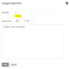
    You should be able to attach the .sal file directly into your response. Choose "Insert --> Image/Video/File". In the pop-up screen, make sure to click "Upload" to select your file (this is not obvious I know). I have shown the pop up screen below

    Before you upload the file however you will need to change the file extension because for some reason .sal files cannot be directly uploaded. So if your filename is "file.sal" for example, change it to "file.sal.xlsx" and then upload it to e2e. I will then download the file and remove the ".xlsx" from the file name to be able to open it as a .sal file. I am not sure why we need to do it this way, but this is the only way it works

    -Bryan

  • TI_data_share.zip
    Hi Bryan,

    Thank you for the reply.

    I have attached the zip file which contain the .sal file and other details as well related to setup and application.

    I have applied analog input signal to channel 0. I have attached analog signal screenshot file and Saleae logic aalyer .sal file.
    I have taken the controller code for reference and ported it for the processor. I have also attached schematic screenshot for the reference.

    Application is reading the spi data after every 30s. I have also attached the Application output file for details.

    Thanks,

    Himanishu 

  • Hi Himanishu Karadbhajne,

    Thanks for sending this over, I was able to see your logic analyzer data

    One thing that immediately jumps out to me is that the SCLK must idle low, not high. This is described in section 8.5.1 in the M02 datasheet. Also make sure that you are reading data on DOUT on the falling edge of SCLK

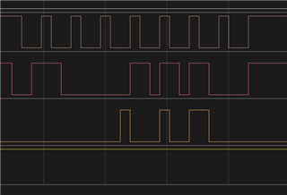
    I also noticed that you have random SCLKs, two of which are shown in the first image below. You should only send SCLKs to the ADC when you are ready to communicate to the device, especially since you have CS held low. I am not sure if your controller is actually sending these SCLKs or if you are capturing transient pulses on the SCLK line. Either way, this is not good and needs to be remedied

    Also, the SCLK duty cycle does not appear to be 50:50, instead it is closer to 33:66. I presume most controllers would not generate such a lopsided SCLK signal, so you might want to check out how clean your SCLK signal is coming out of the controller

    -Bryan