This thread has been locked.

If you have a related question, please click the "Ask a related question" button in the top right corner. The newly created question will be automatically linked to this question.

DDC264: About DDC264 System CLK and Analog Input layout

Part Number: DDC264

  Good day,TI Expert.

  <1> My customer want to use MCU to  control DDC264,but I find out the MCU couldn't run "10Mhz interrupt function" normally to toggle CONV within ±10ns of the falling edge of CLK.

So I want to use Active Crystal Oscillator and Frequency Divider to generate System CLK and CONV signal.What parameter of Active Crystal Oscillator I should notice?In other words,what kind of signal should I provide,like voltage,current,and etc...

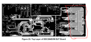
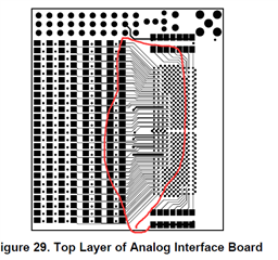
  <2> And I see that the circuitry between Analog Input and sample connentor aren't snake routing to make same impedance in DDC264EVM board.Will it make a obvious difference in different channel when test same sample? If I try to control the same impedance,what impedance should I set,100ohm ± 10 or ...

1

2

  • Hi,

    Sorry not sure I understand the first question... The CONV and CLK signals are described in the datasheet (they are standard CMOS signals...). I guess you could latch externally CONV with CLK falling edge.

    On the second, the current inputs are traditionally slow signals (<KHz). There are no concerns with transmission-line type theory. So, no worries about impedance or delays, but ideally you would still want to minimize parasitic capacitance (to reduce noise) and coupling to any other traces, digital or even DC lines that could leak into them.

    Regards,
    Edu

  •   Good day,TI Expert Edu.

    <1> I understand.That mean I just provide CMOS signals to CLK and CONV will be OK.

    <2> So what could I do like you said that "I want to minimize parasitic capacitance (to reduce noise) and coupling to any other traces, digital or even DC lines that could leak into them".

      Thanks for your reply and suggestion.

      Regards,

      JieYin.