This thread has been locked.

If you have a related question, please click the "Ask a related question" button in the top right corner. The newly created question will be automatically linked to this question.

ADS131E08EVM-PDK: MMB0 Board No Power LEDs On

Part Number: ADS131E08EVM-PDK
Other Parts Discussed in Thread: REG104

Hello,

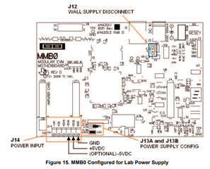
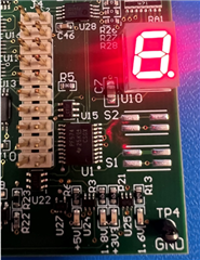
When powering the MMB0 board provided with the ADS131E08EVM through the J2 power jack, I noticed that none of the voltage rail LEDs come on. Only the seven-segment display U10 lights up. I measured about 300mV at the 3.3V test points. The supply I am using is rated for 12V and 1A output, which should be within the required specifications. 

Is there anything I am missing for proper functionality?

  • Hi Emily Marcelo,

    Can you try using a lower-voltage supply e.g. 9V, through the barrel jack connector (J2) on the MMB0? If not, try applying a +5V supply to the MMB0 directly using J14. When using an external bench supply to power J14, make sure to remove jumper J12, set the J13 jumpers, and apply the voltage to the correct pins on J14. This is shown in the image below

    -Bryan

  • Hi Bryan,

    I used a 9V supply through J2 and got the same problem as before. The same thing happened when using an external bench supply through J14 after removing J12 and setting the J13 jumpers. Using the bench supply, I am measuring about 0.109V at the +3.3V test points.

    Is there anything else I should try?

  • Hi Emily Marcelo,

    Where are you measuring the +3.3V voltage? Once you apply the bench supply to J14 you should be able to probe the J5 header on the MMB0 (with the E08 EVM daughter card removed) and measure 3.3, 1.8, and 5V as shown in the diagram below. Note that this diagram shows the jumper as J3 because this is taken from a different daughter card, not the MMB0.

    If you use the external 5V supply and you are not seeing any voltage at these pins, then you might have a dead board

    You can also send me a picture of your setup so I can see if anything is wrong

    -Bryan

  • Hi Bryan,

    I was previously using the point on J6 to measure +3.3V. Probing the J5 header on the MMB0, +5V and +1.8V appear properly. I still measure about 0.109V on the +3.3V pin of J5.

    Here are images of my setup:

  • Hi Emily Marcelo,

    It is interesting that the 5V works but the 3V3 does not. Below is a portion of the MMB0 schematic that shows where the 3V3 is generated. Can you probe on these pins with the MMB0 powered and see if the voltage is correct? Specifically, C41 and R15 should provide the 3V3 voltage.

    If you don't get the correct voltage, then it is possible that the TPS70302 was damaged (you can probe on that 1.6V net as well to see if this LDO is completely non functional). You could try applying an external 3V3 voltage to one of those points near the LDO, or even to the J5 header

    -Bryan

  • Hi Bryan,

    Probing at the pins, I measured about 0.109V at the 3V3 and close to no voltage on the 1.6V net.

    Supplying an external 5V and 3.3V resulted in all LEDs except for 1.6V lighting up. I'm guessing that 1.8V is generated from the 5V rail on a separate regulator while 3.3V and 1.6V both come from the TPS70302, which would explain why only the 1.6V stayed off. 

    Looking at the image you sent, it looks like U5 regulates the input voltage from the J2 power jack down to 5V. I checked the input and output pins of U5 and they were shorted, so it's possible that the TPS70302 was damaged from overvoltage.

  • Hi Emily Marcelo,

    Thanks for performing these tests, it seems we've identified what happened on the board with the REG104 (and you are correct about your assumptions regarding the 1.6V and 1.8V rails)

    You can install the J6 header on the MMB0 and provide an external 3.3V there, if you want to use the MMB0 board that you have. I can also provide you a replacement board, though this will probably take 1 week to arrive. If you want to go this route, I will have our sales team reach out to you offline. Please let me know.

    -Bryan

  • Hi Bryan,

    Thank you for the help! If possible, I would like to have a replacement board sent.

  • Hi Emily Marcelo,

    Ok, I will work to get this done. Can you provide me your email address? If you do not want to provide this information on the public e2e forum, you may send it to me via private message. You can do so by hovering over my name (Bryan Lizon86) and selecting "Request friendship". This allows us to send private messages

    -Bryan

  • Hi Emily Marcelo,

    One more comment: when you receive the new board, I would either use a lower voltage AC power adapter (<=9V), or use the J14 terminal block to power the MMB0. The REG104 has a thermal shutdown mode that can be triggered by excessive power dissipation when the difference between the input voltage and output voltage is large e.g. 12V --> 5V

    -Bryan

  • Hi Bryan,

    Thank you for the suggestion, I will most likely be using the J14 block to power the new board.

  • Sounds good Emily