This thread has been locked.

If you have a related question, please click the "Ask a related question" button in the top right corner. The newly created question will be automatically linked to this question.

AFE4490: Reset design consultation

Part Number: AFE4490

Hi, team:

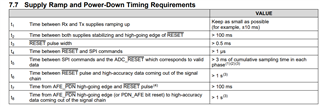
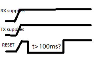
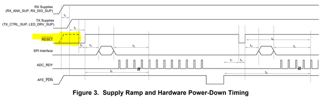
    I noticed in datasheet it described “Time between both supplies stabilizing and high-going edge of RESET >100ms “, I hope to know is this a condition that T2 must meet or it is a suggestion?could you help explain the influence?

     Currently the reset pin adds a pull-up resistor to supply, it will pull up when system powering up, but after that we will reset the 4490 after the MCU is powered on.


  • Hi,

    It's requirement for " “Time between both supplies stabilizing and high-going edge of RESET >100ms “"
    without proper RESET signal and timing, the device may not be RESET properly and could be in some unknown/unexpected state, then the operation and performance may not meet the datasheet spec and unexpected.

    Thanks

  • Hi,

    It's requirement for "Time between both supplies stabilizing and high-going edge of RESET >100ms “"
    without proper RESET signal and timing, the device may not be RESET properly and could be in some unknown/unexpected state, then the operation and performance may not meet the datasheet spec and unexpected.

    Yes, they can do that as EVM also does-

    But, they may want to pull the /RESET pin to low again for >100.5ms after the both supplies stabilizing.

    Thanks

  • Hi, Chienchun:

       I want to check it, do you mean is it need operate like below?


         I have another two questions:

         1.Can 100ms be shorten?

         2. In my customer ‘s project, if there is an abnormal situation, the TX power supply will be turned off, but the RX power supply will always be maintained. In this case, whether it need operate reset pin? and whether it is also need keep more that reset low more than  100ms?


  • Hi,

    In the Figure 3 timing diagram-

    the /RESET starts with dashed/dotted line, usually dashed/dotted line means/indicates don't care about /RESET's state during this period.

    HOWEVER, t2(>100ms) and t3(>0.5ms) are important, that means after the "TX Supplies (TX_CTRL_SUP, LED_DRV_SUP)" is stable, the /RESET pin state must be held/pulled to low state for at least t2 + t3 i.e. > 100ms +0.5ms = 100.5ms before /RESET rises to high state.

    In other words, as described in datasheet "Through a hardware reset by applying a low-going pulse on the RESET pin".

    So, it's recommended to stay/follow with datasheet's suggestion/recommendation.

    So, above is required to have the chip to have proper power up/rest/initialization. 

    If customers want to shorten/shorter than 100.5 ms, they will need to go through a series of tests&V&V to ensure the functions&operations stability.

    ----------------------------------

    2. Thanks. this is important to know.
    Then, may I ask what does customer want or configure the AFE to do when and during the TX Supplies are all shut/turned off AND still keep the RX supplies ON?

    And, will the TX supplies be turned back on again?


    I need to discuss this with other engineers to see whether - 

    1. shutting/turning off TX supplies affect what customer wants to do(please let me know) during off TX supplies. Please let me know what customer want to do during TX supplies off duration?

    2. Whether shutting TX supplies off affect any pre-configured registers settings and/or require any reset or /RESET action after customers turn the TX supplies back on?

    Thanks,