This thread has been locked.

If you have a related question, please click the "Ask a related question" button in the top right corner. The newly created question will be automatically linked to this question.

ADS1298: Hardware Pace using Slope Detection

Part Number: ADS1298

Hi 

My customer are referring to this application note "Hardware Pace using Slope Detection"

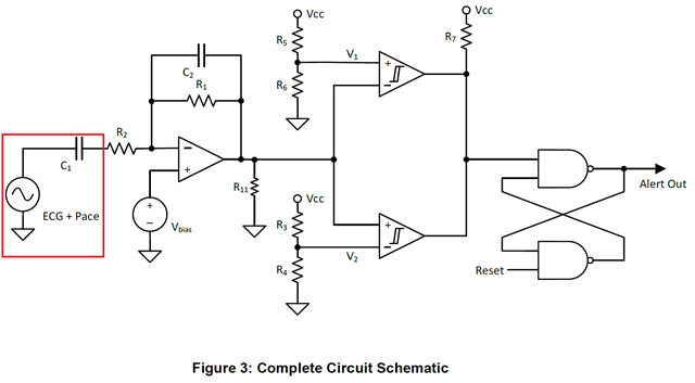
My customer adopt below circuit

two questions need your help 

1. are our register settings correct 

    - Config2: 0x02

    - PACE: 0x01

2. in the red area indicated below (ECG+PACE) where should i connect it to is it TESTP_PACE_OUT1 or  TESTN_PACE_OUT1 ?


  • Hi,

    This is related to "pace detection by using " "External hardware".

    So, They will need to " bringing out the output of the PGA at two pins: TESTP_PACE_OUT1 and TESTN_PACE_OUT2."

    -------------------------

    Take a look of  9.3.1.7.7.2 External Hardware Approach and Figure 46.

    First, to be able to use the PACE Amp to route/bring the PACE signal out, they need to set /PD_PACE 1 = Pace detect buffer turned on.

    In order to "connecting external hardware to the output of the PGA to detect the presence of the pulse.", 

    The pace output signals are multiplexed with the TESTP and TESTN signals through the TESTP_PACE_OUT1 and TESTN_PACE_OUT2 pins, respectively. Channel selection is achieved by setting bits[4:1] of the PACE register.

    So, the input to the external PACE detection circuit should come from ADS1298's

    either 

    TESTN_PACE_OUT1 pin or TESTN_PACE_OUT2 pin.

    Let's say if they want to bring the PACE signal out from TESTN_PACE_OUT1 pin, then they will need to use

    PACE[4:3] register bits to select which channel they want to route the PACE signal to the "PACE Amp" for TESTN_PACE_OUT1 pin.

    e.g.  if they want to route/bring PACE signal from Channel 2(PGA2) to TESTN_PACE_OUT1 pin, then they will set PACE[4:3] to 00 to close/short the "Pace even channel" switches; take a look of Figure 46 and Table 31.

    -------------------------------

    Above enables&allows to bring the PACE signal out to TESTP_PACE_OUT1 pin for external hardware pace detection.

    ----------------------------

    Regarding to the signal after the external hardware pace detection circuit -

    The Alert Out can either be connected

    1. directly to the host/master's GPIO pin

    or

    2. back into ADS1298 by following "The output of the pace detection logic is then fed into the device through one of the GPIO pins." E.g. "GPIO1 can be used as the PACE_IN signal."

    e.g. if use/select GPIO1 to take/receive the Alter Out, GPIOC1 needs to be 1 for input.

    Thanks