This thread has been locked.
If you have a related question, please click the "Ask a related question" button in the top right corner. The newly created question will be automatically linked to this question.
I hope someone can please help, I am on a deadline to collect some important data ASAP:
I first want to give some background:
In 2011 I purchased a ADS1278EVM-PDK evaluation kit. At the time I loaded ADCPro onto my trusty, and still my best Windows-XP 32-bit data collection computer.
Long story short, the hard drive got wiped on my computer, and everyone knows that this is not fast recovery for anyone that uses there computer daily.
But, TI and their excellent customer service kicked in, Mr. Hendric sent me a new EVM, but no MMB0 (may be the issue?).
He even went out of his way by sending me the hard drive out of his laptop!
I retried to get the ADCPro working again, but to my surprise I was awarded a patent after a long battle with the USPTO.
I could not make any progress with the ADCPro and ADS1278EVM-PDK evaluation kit, so I abandoned the EVM until now, 2023.
Last week I loaded a fresh copy of ADC Pro v2.0.0 build 4 onto a fresh install of Windows-7 64-bit onto a NUC 5i5 with 16GB of memory.
Also I loaded the latest ADS1278EVM-PDK package which was down loaded with the above software.
After many years of time, and too many hours of experimentation, I got the EVM to read.
WHAT I THINK:
a) I may need a different set of drivers for the 64-bit machine, if so please give URL and instructions on how to load them.
b) Once going through the routine below, I can use 'Acquire' to read the ADS1287 with one channel, that is until ADCPro will lock up and I have to use Ctrl + ALt + Delete to kill the process and start over by reboot.
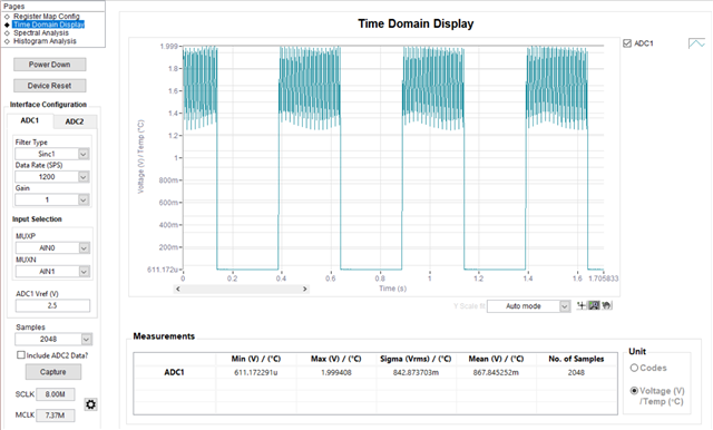
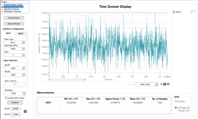
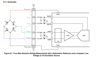
c) I really need to solve this issue ASAP, I am going to do precision instrumentation such as found in TI document sbaa532.pdf.
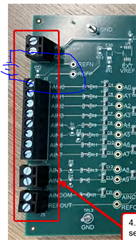
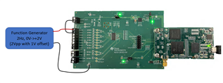
I want to use the on-board 2.5Vref to excite the bridge and get a ratiometric measurement.
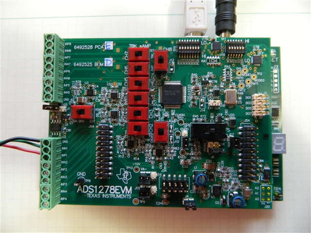
d) I have document.pdf, but there is no ID for the BOM or which version of ADS1278EVM board I have?
I know this EVM was in the initial stages of development when I got the kit.
ROUTINE AND DETAILS -- STARTUP ERROR MESSAGES AND SEQUENCE:
DEVICE MANAGER (Plug in EVM to USB, Power up EVM, then load ADCPro):
When the MMB0 board is connected, the following driver is loaded:
NI-VISA USB Devices > expand driver tree
MMB0 (NI-VISA) >
Start ADCPRo >
When 'ADC1278EVM' is loaded from ADCPro EVM (menu), device manager removes 'NI-VISA USB Devices' driver and loads :
libusb-win32 devices >
ADC1278EVM (left window at top message) reads: Connected to EVM (in green font)
> Only USB type driver in DEVICE MANAGER is: USB Virtualization > expand driver tree
USB Virtualization Connector Driver >
turn off all but CH1 with software 'Manual Control' power up/down (no change in DEVICE MANAGER drivers) >
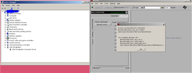
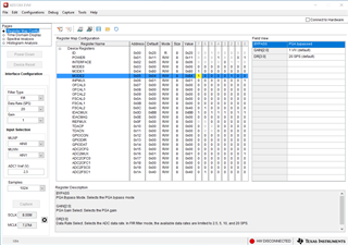
ADCPro gives error message Code 6004, see image: Load_EVM-ADCPro-PowerDown_CHx.PNG >
OK (only option) >
ADC1278EVM (left window at top message) reads: Connected to EVM (in green font)
Load 'File Reader' from ADCPro EVM (menu) >
Load 'ADC1278EVM' from ADCPro EVM (menu) >
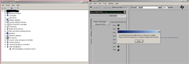
ADC1278EVM (left window at top message) reads: Load failed.. reset the hardware (in green font) >
ADCPro gives error message (no code), see image: Reload_ADS1278EVM-PDK.PNG >
Exit (only option) >
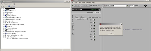
ADCPro gives error message Code 6070, see image: 3)Post_Exit-Error.PNG >
OK (only option) >
ADC1278EVM (left window at top message) reads: -TIMEOUT- (in green font) >
RESET (button on MMB0 'S3') Note that '8' is fully illuminated on the MMB0 >
DEVICE MANAGE flashes as though drivers are refreshed and:
REMOVED:
libusb-win32 devices >
RELOAD:
NI-VISA USB Devices > expand driver tree
MMB0 (NI-VISA) >
Same routine of removing & reloading EVM:
Load 'File Reader' from ADCPro EVM (menu) >
Load 'ADC1278EVM' from ADCPro EVM (menu) >
ADC1278EVM (left window at top message) reads: Connected to EVM (in green font) >
Turn off all but CH1 (same driver routine as above when EVM loads) >
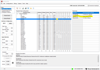
Low-speed Operating mode and CLKDIV Control = 0 (settings left vertical tab) >
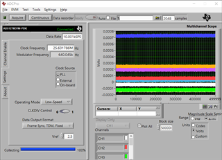
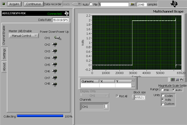
Load 'Multiscope' (test menu) >
All default settings except 'Data Rate 10.547kSPS' >
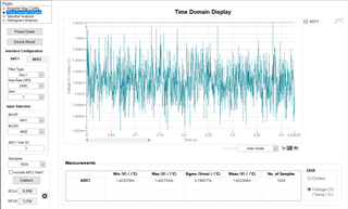
Acquire (button top menu) >
Open CH1 reads 60Hz noise in laboratory (not change in DEVICE MANAGER drivers) >
Ctrl + ALt + Delete (keys) >
Task Manager Performance Tab >
* Looks like only 2 of 4 CPUs are used, 9% while ADCPro is running.
* 1.64 GB of 16GB Memory used while ADCPro is running.
If I plug in a thumb drive the DEVICE MANAGER loads this driver (in addition to what is above):
Universal Serial Bus controllers (with tree to expand to see USB controllers and mass storage device, hub,...)
Hello Paul,
Can you confirm the board version of your EVM? It would be helpful if you could provide a picture of both the MMB0 board and the ADS1278EVM board to help track down any possible hardware configuration issues.
Also, what is the voltage of the external power supply used to power the EVM? The recommended voltage level should be between 6V and 7V. The board will accept higher voltages without damage, but if the voltage is higher than about 8V, the EVM will work for a few minutes until the on-board linear regulator overheats and shuts down. This would result in the initial correct operation, but then getting similar error messages that you have recorded.
The ADCPro software should work well on a Windows 7 machine, and we updated the drivers to signed drivers a few years ago to support installation on Windows 10. However, this does not rule out that virus software may prevent the proper installation of the drivers, regardless if they are signed or not signed.
a) We do not have any additional drivers for the software; the drivers that come with the installation package are the only drivers available and should work on both 32b and 64b Windows installations.
b) Does the EVM initially work and capture data, at least for one of the channels? If this is the case, this implies the software drivers have been properly installed. As I had previously mentioned, this seems more like a hardware issue, and could be caused by an external power supply voltage greater than 7V.
c) Since you need to take ratio-metric measurements of a bridge sensor, we do have better suited ADCs for this application, such as the ADS1262. The ADS1278 does not include internal reference or input buffers. In order to use the ADC for this application, you would need to add external amplifiers for both the input channels and the reference. The ADS1262 integrates reference buffers, a PGA, and an input multiplexor.
d) Please provide a picture of both the ADS1278EVM and the MMB0 data capture board.
Regards,
Keith Nicholas
Precision ADC Applications
The power supply is the TI 120VAC supply that came with the EVM.
I have been able to collect data, but for brief periods of time before computer locks up or I get an error message and computer lockup.
The W-7 install is fresh, only necessary updates.
No malware programs on this computer, just ADCPro and MS-Excel.
When doing data collection only ADCPro is running.
First time I start program and use the EVM, will get error message, have to load twice to read data. The MMB0 board seems to be the problem, as mentioned a new EVM module seen in the photo was sent to me by a TI employee that was developing this product in 2011.
I am using one channel, without Input Buffers, I am using an INA849 input amplifier.
There is both an REF5025 and REF3125 onboard the EVM.
Here is a photo of the EVM:
This is very frustrating as this tool has never worked without computer locking up.
The settings are as per the instructions, if you can add some inside, you should be able to see all the jumper settings in this photo.
Seems to be able to run at the default clock speed with 512 samples longest, when I slow down the clock and try and get more samples, say 3 seconds, seems to lock the system up often.
I could not find modern documentation, I am using SBAU129D and ABAU142A for ADCPro, EVM, and MMBO.
Any better documentation and settings help would be appreciated:
Such as, best clock and max number of sample, jumper and/or switch setting to get for a 3 second data collection period.
Hello Paul,
I do not think the EVM hardware is damaged or the drivers are not correctly installing. Since you are able to collect data, this indicates that the hardware and software installation are working. I am able to reproduce the errors you see when connecting the EVM through multiple USB hubs. It always works with 512 samples, but increasing to 5000 samples always results in a lockup of the software.
Suggestions to fix the lockup:
1. Connect the EVM directly to the root hub on your PC, if not already connected.
2. If the errors still occur, try using a different PC, especially if the Window 7 machine is an older machine.
I am using a 2018 HP Elitebook running Windows 10 and am able to collect 500k samples of data over 10's of seconds with no issues. If I connect the EVM through a hub, I can not collect more than a few thousand samples before it locks up, similar to your observations.
Below is an example, sampling at 10ksps for 50 seconds (500k points), which is near the maximum limit for the MMB0 memory.
The documentation that you have should be the correct version for this revision of the hardware.
Regards,
Keith
Hi Keith, all I can figure is that I have always had a defective MMB0 from the get go.
I worked all morning with different settings and I could not prevent the computer from locking up. I am using an NUC 5i5 with 16 GB memory, not using a USB hub, have tried both USB 2.0 and 3.0, nothing works. Either the ADCPro locks up, or I get error message after error message.
Darn, I had it working for about an hour, then boom, lack of cooperation from the EVM
I ordered an ADS1263EVM, if TI could find it in their hearts to give me a credit it would be appreciated. I can send the 1278EVM to you if you like, I have two EVM boards and the MMB0.
I would say I have about a week of effort over the years trying to get this thing working. I used multiple computers and both XP and W-7, must be a hardware issue this whole time.
I know that the NI drivers conflicted with my Tektronix scope, this is why I choose to use a fresh install of W-7 without any programs other then MS-Excel 2003 loaded on the computer.
Thanks for your help, TI has the best customer service :)
This is the first time I have had an issue like this with a TI product.
Hi Paul,
Unfortunately, I do not have a way to provide any kind of credit. I could probably replace the existing ADS1278EVM, but it is out of stock, and for temperature measurements, there are better parts. The ADS1263 is one of our best devices for any kind of temperature measurement, including thermistors, RTDs, and thermocouples.
Regards,
Keith
Hi Keith,
What a disaster, I over night the ADS1263EVM, apparently if fell off of the outgoing bench, it showed up 5 days later. I ordered another product from another company, and I got the job done with it.
So, I connect the ADS1263EVM to a signal generator, and the my Tek scope (8-bit).
The ADS1263EVM does not seem to be able to connect the dots on a saw-tooth wave.
Tried different data rates, filters, Vref as internal and power supply, the curve is ugly!
Any suggestions, looks like it just does not connect the dots, what you cannot see in the screen capture, there is a noisy GND signal connecting the dots below.
Some kind of MUX setting?
I have the EVM setup just like in the ADS1263 datasheet showing a load cell bridge.
The external power supply Vref and internal 2.5Vref are the same.
Hello Paul,
The software should 'connect the dots'. It looks to me like the input is going below ground. Please confirm that the AINP and AINN inputs are in the range of 0.3V to 4.7V relative to ground.
Regards,
Keith
OK, the signal you see above is a sawtooth wave from 0 to 0.08V @ 50Hz.
This is what I read on my Tek scope.
So, plan-B, application of KISS:
Below is a AAA battery, pure DC, all input filters gave the same result. These are the default settings for the program. The disappointing fact, ADCPro, when not locked up, read the above sawtooth wave perfect. Also, ADCPro one had a lot more control over the plot, when there was date to control.
Turning in to a time sink, or has been one.
Hello Paul,
Please try this setup. First, in order to measure a signal near ground with the EVM, you need to set the internal PGA to Bypass mode. Go to the Register Map Config page, select the MODE2 register, and set the BYPASS bit to 'PGA bypassed'.
Next, using the default inputs, connect the AIN1 pin to ground, and connect your source (battery) between AIN0 (positive input) and ground.
You should not be able to accurately measure voltages between 0V (ground) and 2.5V (Vref).
Regards,
Keith
Hi Keith, time sink it is, please report my findings to the TI store:
I had to tear apart my computer to put in the hard drive with W-7 64-bit that had ADCPro on it.
Above is one of those fleeting moments where the ADCPro connected and worked with the ADS1278EVM (giving me hope and absorbing more time). This is an accurate representation of the 0-2V, 2Hz, square wave from a signal generator. Although I did not see the ringing on my scope, this is a very accurate differential input representation of the signal. And, the low component of the square wave reads zero! Thus, one would think that the ADS1263 would be capable of the same kind of measurement? Well let's test it:
Here is the same signal generator with the same signal seen above on the ADS1278.
The PGA is bypassed and AN1 is grounded. Note that the signal is filled with noise at the 2V high, the measurement is incorrect regarding the measured voltage. This is consistent, and excitedly aggravating given the issues that the TI store knows of, and I hope to address. They quit talking to me, will you be my ambassador?
Finally, this next image is of a load cell with a precisely measured static load. My Fluke measures the correct output, 1.03mV. The figure above is an ADS1263 ratiometric 32-bit adc measurement, one cannot ground the AN2 for this type of measurement, it has to be a differential measurement. The results are the same with PGA bypassed or not. The error just increased with PGA G=32 due to the internal ADS noise. Scope reads no noise on the signal, another bad experience. Up to this point I have always had success with TI parts and EVMs. I bought this device to read high speed dynamic signals with accuracy.
If you do not accept this mission, the post will burn in 30 seconds
Hello Paul,
Please send a connection diagram or a picture of your connections between your function generator and the ADS1263EVM. I am not able to explain what you are measuring. Below is the same setup that you have, 2Vpp, 2Hz input, gain=1, PGA bypassed.
Also, please send a connection diagram with your load cell, including all register settings. I assume you have everything connected as shown below, with the reference internally connected to REFP=AVDD and REFN=AVSS. Also, the typical offset for Gain=1 is 350uV. You can eliminate this offset by enabling Input Chop in the MODE0 register.
Regards,
Keith
Hi Keith, to respond to your comment "I am not able to explain what you are measuring." neither am I able to explain the signal I sent you given that using my Tek scope I see a perfect signal from the signal generator. I am connected to the signal generator by a BNC and a BNC to screw terminal block as is on the EVM board with very short 18AWG wires.
As far as the load cell, it is disconnected at this point. Can you see the noise on the load cell? I feel I am back to wasting time, and I really need to get satisfaction here. Can you explain it, and yes, as I have said, the load cell is connected just like the figure in the datasheet. Why is it that with a static load, that is it is the load is not changing, my scope reads it correctly with out noise (just like the signal generator (pattern)?
I find it hard to understand how a new EVM board puts out such a bad signal, did you look at the same signal with the same cable seen on the ADS1278EVM? Same setup, different outcome with 1263!
I seem to have bought two EVM boards that just do not work. What can be done about this?
The ADS1278EVM should = ADS1263EVM = Scope, and they do not.
If the ADS1263EVM had a signal I could depend on, then I would try enabling Input Chop in the MODE0. But, I purchased this device on your recommendation to capture a transient form a load cell, I wanted at leas 16-bits of vertical resolution. I cannot trust the signal when you look at the signal generator viewed on the ADS1263EVM due to the noise seen in the square wave.
To add insult to injury, I had it sent next day air, it showed up around 5 days later.
TI store said that they would compensate me and work with me, that seems to be for another day?
Paul
Hi Paul,
Just to add to the above ADS1263 square wave capture, here is how I connected the function generator to the EVM board. This is the default GUI configuration with MUXP connected to AIN0 and MUXN connected to AIN1. These boards are fully tested at the board house before shipment but not impossible for something to go wrong after test. If this is not how you had it connected previously, please try this approach to see if you can get the correct results.
Regarding the load cell data, this data is exactly as expected (The display is zoomed in quite a bit verses the full scale input range of 10Vpp.) Using a Gain=1, SINC1 filter, and data rate of 2400sps, the expected RMS noise is 3.4uVrms and the peak-to-peak noise is 26uVpp, which is very close to the measurements that you made. Scopes usually have a much lower resolution, and it is not possible to see this level of noise. Based on these measurements, I would say that the EVM is working as expected. In order to reduce the noise, you should use the highest gain possible without saturating the ADC inputs. The other option to reduce noise is to use the lowest data rate possible, but of course, the tradeoff is a slower response time.
Also, the offset voltage will be a typical of 350uV when using a GAIN=1. This offset voltage will also be reduced with higher gain settings, and can be eliminated with Chop Mode.
Regarding the results between the ADS1278EVM and the ADS1263EVM with external function generator, the two EVMs have a different input topology.
Although both EVMs are differential inputs, the ADS1278EVM uses a low input impedance amplifier that will self bias to the required input common mode voltage levels. In other words, you can connect a floating input source (battery operated function generator or a simple 1.5V battery between the AIN0 and AIN1 terminals), and the EVM input channel will be able to correctly measure the source voltage without any other connections.
The input structure on the ADS1263EVM is very high input impedance to reduce errors when connected to a bridge sensor, such as a load cell. In this case, there must be a common mode connection to the EVM ground. A bridge sensor driven by the EVM will provide this common mode path to ground. In the above configuration, I used a piece of wire to directly connect the AIN1 input (MUXN) directly to the EVM ground. I then connected the external function generator positive output to the AIN0 input (MUXP) and connected the negative output (BNC shell) to the Ground test point on the EVM to complete the circuit.
Unfortunately, the ADS1278 board that you have is very old and may not work well with the latest version of ADCPro that has been updated to work on Windows 7, and drivers updated to work with Windows 10.
Sorry about the delayed 'overnight' delivery. Hopefully the TI Store can correct this error.
Regards,
Keith
Please see inline response:
Hi Paul,
Just to add to the above ADS1263 square wave capture, here is how I connected the function generator to the EVM board. This is the default GUI configuration with MUXP connected to AIN0 and MUXN connected to AIN1.
If you go up and look, you will see that this is how I connected the function generator.
FYI, look to the left in the photo to see the ports. I also gave the register settings.
These boards are fully tested at the board house before shipment but not impossible for something to go wrong after test. If this is not how you had it connected previously, please try this approach to see if you can get the correct results.
Nope, does not work, but thanks for they try. Still sucking up my time!
Regarding the load cell data, this data is exactly as expected (The display is zoomed in quite a bit verses the full scale input range of 10Vpp.) Using a Gain=1, SINC1 filter, and data rate of 2400sps, the expected RMS noise is 3.4uVrms and the peak-to-peak noise is 26uVpp, which is very close to the measurements that you made. Scopes usually have a much lower resolution, and it is not possible to see this level of noise. Based on these measurements, I would say that the EVM is working as expected. In order to reduce the noise, you should use the highest gain possible without saturating the ADC inputs. The other option to reduce noise is to use the lowest data rate possible, but of course, the tradeoff is a slower response time.
Sorry, I need accuracy, this is why I bought and overnight mailed this board.
I did try a gain of 32, there is too much noise to get a good reading from the load cell for a fast event, which is why I bought the board.
Also, the offset voltage will be a typical of 350uV when using a GAIN=1. This offset voltage will also be reduced with higher gain settings, and can be eliminated with Chop Mode.
I am tired of spending time on this, sure the Chop Mode may do it, but this is the same story as with the ADS1278, it just went on and on trying to make it work. The square wave for the ADC1263 speaks volumes.
Regarding the results between the ADS1278EVM and the ADS1263EVM with external function generator, the two EVMs have a different input topology.
Well then I do not like either one of them, the ADS1278 software sucks, and the input topoligy sucks on the ADS1263 apparently if this explains the square wave results.
Although both EVMs are differential inputs, the ADS1278EVM uses a low input impedance amplifier that will self bias to the required input common mode voltage levels. In other words, you can connect a floating input source (battery operated function generator or a simple 1.5V battery between the AIN0 and AIN1 terminals), and the EVM input channel will be able to correctly measure the source voltage without any other connections.
Yes, this is how a differential input should work.
The input structure on the ADS1263EVM is very high input impedance to reduce errors when connected to a bridge sensor, such as a load cell. In this case, there must be a common mode connection to the EVM ground. A bridge sensor driven by the EVM will provide this common mode path to ground. In the above configuration, I used a piece of wire to directly connect the AIN1 input (MUXN) directly to the EVM ground. I then connected the external function generator positive output to the AIN0 input (MUXP) and connected the negative output (BNC shell) to the Ground test point on the EVM to complete the circuit.
So you are saying I need an instrumentation amplifier on the front end to the ADS1263?
Unfortunately, the ADS1278 board that you have is very old and may not work well with the latest version of ADCPro that has been updated to work on Windows 7, and drivers updated to work with Windows 10.
You do not see to understand, the ADS1278 has never worked, and I am tired of expressing this.
Sorry about the delayed 'overnight' delivery. Hopefully the TI Store can correct this error.
The TI store did reach out to me, they said if I responded to the E2E that they would take care of me. So, let's see what that means?
As I said, I have always found TI parts to be some of the best on the market, this whole ADS thing just has got to the point that I am getting angry due to the time spent going round and round.
Regards,
Keith
Hi Keith, well I went back and did the test seen in the post above where I stated:
"The PGA is bypassed and AN1 is grounded. Note that the signal is filled with noise at the 2V high, the measurement is incorrect regarding the measured voltage."
I followed your advice:
"here is how I connected the function generator to the EVM board. This is the default GUI configuration with MUXP connected to AIN0 and MUXN connected to AIN1."
But, on the first tests in the above post, I grounded to the screw terminal ground, this time I grounded to the lug as you did. I also tried some different register settings, I really like the new interface compared to ADCPro other than not being able to scale the plot.
I am sorry to say that I got the same results, just spent more time doing it.
I believe I have another defective board.
The gentleman at the TI store said this:
"Thank you for letting me know. Yes, kindly advise that issue is not fix and if it is possible for a refund."
Apparently the TI store is willing to give me a refund if you can authorize it?
Please let me know, it would be much appreciated, I will point the TI store back to your response.
Paul