This thread has been locked.

If you have a related question, please click the "Ask a related question" button in the top right corner. The newly created question will be automatically linked to this question.

ADS124S06: Manual AC Excitation: Reference pins polarity

Part Number: ADS124S06
Other Parts Discussed in Thread: ADS1235

Hello,

I will be using the ADS124S06 in a wheatstone bridge application, and will be using manual AC excitation given that this ADC does not have the control logic integrated.

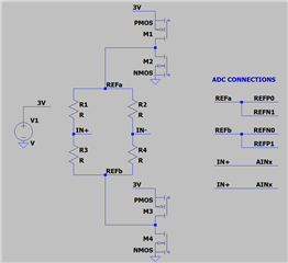
I have attached a simplified diagram - essentially my question is whether it is OK for the REFP/N pins to experience alternating polarity during the AC excitation sequence.

For example,

  • While M1 & M4 are on:
    • REFP0 = 3V (selected reference)
    • REFN0 = 0V (selected reference)
    • REFP1 = 0V
    • REFN1 = 3V
    • In this scenario REFP1 - REFN1 = negative 3V.  Although this would not be the selected reference via SPI commands.
  • While M3 & M2 are on:
    • REFP0 = 0V
    • REFN0 = 3V
    • REFP1 = 3V (selected reference)
    • REFN1 = 0V (selected reference)
    • In this scenario REFP0 - REFN0 = negative 3V.  Although this would not be the selected reference via SPI commands.

So, essentially the question is whether REFP/Nx can sustain a negative 3V voltage temporarily during the AC excitation phase?  The TI example application note TIDUBL0A appears to do it this way, but I wanted to verify - specifically for ADS124S06

.

  • Hi ka88,

    This can be accomplished with some effort both in hardware and firmware.  With AC excitation what is often missed is the requirement for allowing enough delay for analog input settling.  Also, AC excitation may not provide enough benefit as opposed to a single excitation mode.  Have you seen A Basic Guide to Bridge Measurements?  This is a useful resource.

    The reference inputs when not selected do not really have a negative (with respect to AVSS) input voltage and are within the allowable input range for the inputs.

    Have you looked at the ADS1235 which does have excitation control built into the device for AC excitation?

    Best regards,

    Bob B

  • Hello Bob,

    Understood on the fixed delay, we can characterize the settling time and input that to the ADS124S06 register setting.  The ADS1235 is not a suitable candidate for this application given we are single-cell battery powered - so the 5V AVDD and high current consumption of the ADC is not desirable.

    Good point that when the reference inputs are not selected via the multiplexer (and I guess even when they are selected) they do not have a negative bias with respect to AVSS.  The reason I asked was because I was not sure of the internal I/O structure on those reference inputs - for example if they have an ESD structure at the pad which may conduct or otherwise cause damage.

    But it sounds like whether REFPx or REFNx is at 3V or 0V in this application will not cause any damage - regardless of the internal reference multiplexer settings, correct?  I guess I was looking at Table 7.3 in the datasheet, whereas this condition would violate - but I think the point is the measurement will not work correctly (obviously), but at least no damage will occur because the Abs Max conditions are met.

  • Hi ka88,

    Section 7.3 table data shows limits for proper operation.  So if the REFN input is greater in voltage value that REFP you would be out of the specification for proper operation if that reference input were to be selected and used.  And you are correct about the Absolute Maximum Ratings as they must be met.  In your application this use case is not violating those specifications.

    But there is a tricky part in that all this switching doesn't come for 'free' as there will be lengthy analog settling that must be accounted for.  Also, there will be a cross-over region when changing the reference selection where the reference will become invalid.  Here I would recommend temporarily switching to the internal reference while the external reference is settling between the changes of excitation direction.

    This process becomes very complicated and slow.  It is not clear to me why you want to use AC excitation in the first place.  I would highly recommend attempting to see if you can get by without using it.  If there are offset drift concerns, you would be much better off using global chop mode instead.

    Best regards,

    Bob B