This thread has been locked.

If you have a related question, please click the "Ask a related question" button in the top right corner. The newly created question will be automatically linked to this question.

AMC1336EVM: Clock idle risks and INN not connected to GND_ISO

Part Number: AMC1336EVM
Other Parts Discussed in Thread: AMC3336, AMC1336

Hi all,

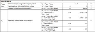
I saw similar parts (if I am right AMC3336), which require a resistive path from INN to GND. From what I understand, the AMC1336 doesn't requires to have such a path. Is it OK when I connect a 1V voltage reference to the INN pin and a signal that goes from 0 to 2V to the INP pin? Given the figure 40 of the datasheet, I would say it is permitted? Should I use a differential amplifier with 1V common mode output?

Second question was about the risks having the clock in idle mode (not clocking at all). It is mentioned that biasing current increases significantly when no clock is provided. Is there any risks not to provide a clock signal for a relatively long time (days)? What should I take in consideration for this to be OK?

Thank you.

  • Hi Fabien,

    Thank you for your question! Per section 6.3, as shown below, using 1V for INN and 0-2V for INP should be fine.

    Having clock in idle mode is fine, but as section 7.3.4 mentions: "When the clock signal is paused or missing, the modulator stops the analog signal conversion and the digital output signal remains frozen in the last logic state. When the clock signal is applied again after a pause, the internal analog circuitry biasing must settle for proper device performance. In this case, consider the t_ASTART specification in the Switching Characteristics table."

    I hope this helps.

    Best,

    Samiha

  • Hi Samiha,

    Many thanks for your support!

    I have already read the table you share, but the doubt persisted because of the statement I found in other datasheet of similar devices from TI: "There must be a resistive path from INN to the ground". It was not clear if 10Gohm is still a resistive path... Anyway, it concerns another device (Chapter 8.3 of AMC1333 datasheet).

    Regarding the clock in idle mode, I asked because I thought that the increase of biasing current at the input during the clock OFF period could damage the inputs. I also thought it would require the front-end to have appropriate circuitry to limit this current.

    Now, with your answer, I know I can go the way I thought without to damage the device. Thanks again.

    Kind regards,

    Fabien

  • Hi Fabien,

    You are most welcome! Although the input bias current (typical 3nA) may increase a little past its range when clock is idle, it should not increase to 10mA, which is when the input pin may be damaged. So, you do not have to worry about this.

    Best,

    Samiha

  • Hi Samiha,

    Many thanks :-)

    Best regards,

    Fabien