This thread has been locked.

If you have a related question, please click the "Ask a related question" button in the top right corner. The newly created question will be automatically linked to this question.

AFE881H1EVM: SPI read issue with AFE board

Part Number: AFE881H1EVM
Other Parts Discussed in Thread: AFE781H1

I am working with the TI AFE781H1 Hart Modem.


I am trying to read write to the registers in SPI Mode.

I'm using STM32U575 controller as master for the AFE.

SPI configuration parameters:

In full-duplex mode, for a 1 MHz clock speed in Mode 2, 

  1. Clock Polarity (CPOL): 1 (Clock is high when idle)
  2. Clock Phase (CPHA): 0 (Data is sampled on the first edge of the clock)
  3. Clock Frequency: 1 MHz
  4. Data Order: MSB (Most Significant Bit) first 
  5. Number of Data Bits: 8 bits 
  6. Data Transmission Direction: Full-duplex 
  7. Chip Select (CS) Management: Active low

setting the UART_DIS bit to 1 to disable UART, DSDO bit to 0 to enable SDO, CRC_EN bit to 0 to disable CRC in register CONFIG.

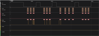
I am looking for confirmation that I am sending the correct sequence of bytes and with the correct timing.


Here is my sequence:

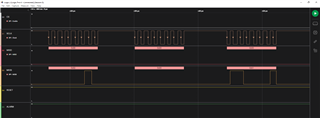
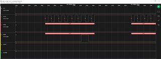
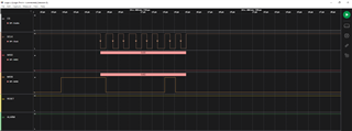
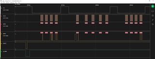
1. doing hardware reset as per sec 7.4.2

2. Sending 3 bytes for register CONFIG (SDI = 0x02, 0x00, 0x61).

3.sending read CONFIG register value (SDI = 0x82). 

4. Sending   NOP command  (SDI = 0x00, 0x00,0x00) 


After executing this sequence, no data on SDO line.


One of my main questions is, what issue causing the SPI read register value.


Do you have any application notes besides what is in the data sheet that describes how this sequence should be done?

  • Asha,


    Let's start with just checking the SPI first. I think using CPOL=1 and CPHA=0 is correct, but to be sure can you just send a zoomed in look at the first communication to the device. In your case, the clock should idle high, and the data should be shifted out on the rising edge of SCLK and sampled on the falling edge of SCLK.

    Show the first transaction going to the device. This would be the four bytes turning off the CRC. Zoom in enough to that I can view and line up the rising and falling edges of the SCLK. Note that /RESET is active low. From your plot, it looks like your device is still in reset while you are communicating with the device.


    Joseph Wu

  • attached data sampling images

  • Asha,

    It looks like the SPI is set up correctly. However, the device is starts off with the CRC enabled. Even if this command is to shut off the CRC, the CRC is still enabled, and this command should be sent with the CRC. If you want to disable the CRC, the first transaction should be sending four bytes: 0x02 0x00 0x26 0x24 with the last byte as the CRC. 

    Joseph Wu

  • Joseph,

    I've enabled CRC bit in config register. no data on SDO line for CONFIG register.

    what could be the issue causing the SPI read register value?

    Asha

  • Asha,


    I looked at the Saleae plot that you sent. In the plot, the bits you sent are 0x02 0x00 0x75 0x77. This would enable the SDO to be driven (instead of being Hi-Z). However, I think the CRC is incorrect. The CRC is a standard CRC-8 and I think the CRC byte should be 0x9A instead of 0x77. I would also note that you could have shutoff the CRC, but it's still enabled here.


    Joseph Wu