This thread has been locked.

If you have a related question, please click the "Ask a related question" button in the top right corner. The newly created question will be automatically linked to this question.

ADS42JB49: Jump in voltage data

Part Number: ADS42JB49

Hi,

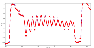
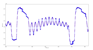
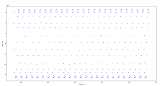
We are seeing interesting voltage jumps in our data. I've attached some captures for reference (red shows individual samples from our signal, middle blue is the signal with connecting line between samples from another capture, and last blue is a 10MHz square (or possibly sine) wave from a signal generator). Do you have any ideas on what might be wrong?

We use the following ADC configuration:

Register

Value

0x6

0x80

0x7

0x00

0x8

0x98

0xB

0x00

0xC

0x00

0xD

0x6C

0xE

0x00

0xF

0x00

0x10

0x00

0x11

0x00

0x12

0x00

0x13

0x00

0x1F

0x7F

0x26

0x04

0x27

0x03

0x2B

0x00

0x2C

0x00

0x2D

0x12

0x30

0x40

0x36

0x00

0x37

0x00

0x38

0x00

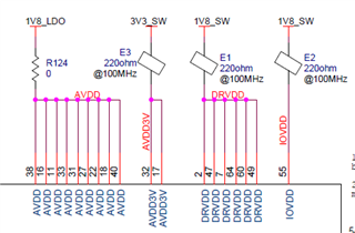
Our power source comes from an LDO (shared with other ICs) and a switcher (shared with other ICs) but separated by ferrite beads. 

  • Hi Sharon,

    I am looking into this. Would you be able to send us the full schematic and provide more details about your test setup?

    One question comes to mind, are you using an amplifier to drive the ADC?

    Also, I have a few questions on the SPI writes:

    1. Are you using channel B? Register 0x8 is configured to power down channel A.

    2. The User Guide configuration sets 19 frames per multiframe and you are programming 18 frames per multiframe. Is there a specific reason for choosing this value?

    Best regards,

    Drew

  • Hi Sharon,

    Could you also please specify your sample rate?

    Best regards,

    Drew

  • Hi Drew,

    Sample rate is 200MSPS. 

    Unfortunately, I cannot share the full schematic. If you have questions about specific parts of the schematic or if there is a more private way for me to send you the schematic, I am happy to share more.

    We had a front end amplifier but something about the connection between the two were causing oscillations so now we are directly injecting a signal that is within the input voltage limits into the ADC directly. 

    We are using channel B, not A. I am using 19 frames per multiframe but the configuration parameters for K must be the binary value - 1 so that is why it is represented as 18. In the FPGA, I set K to be 19 and I see in the ILAS section that setting the ADC K to be 18 allows the two settings to match up and be verified by the FPGA.

  • Thank you Sharon for the details,

    We would still like to know more about your test setup. What are you using to supply your signal? Is it a pulse generator? What is the part number?

    I will send you an email about obtaining schematic information.

    Best regards,

    Drew