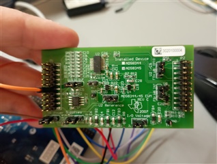
Other Parts Discussed in Thread: ADS8344,
I have an evaluation board including a Cortex M4 MCU from a different vendor. Board has VDD = 3V3 , GND, 5V, DAC. As you guess I don't have different ground planes such as DGND, AGND.
Please see the information below.
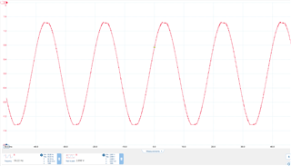
I am feeding a sinusoidal signal to CH5,
My SPI RX Data structure is:
union ADS8344{
	uint8_t reg;
	struct{
		uint8_t PD0:1;
		uint8_t PD1:1;
		uint8_t SGL_DIF:1;
		uint8_t res:1;
		uint8_t A0:1;
		uint8_t A1:1;
		uint8_t A2:1;
		uint8_t S:1;
	}u8reg;
};
  spi_tx.u8reg.S = 1;
  spi_tx.u8reg.A2 = 1;
  spi_tx.u8reg.A1 = 1;
  spi_tx.u8reg.A0 = 0;
  spi_tx.u8reg.res = 0;
  spi_tx.u8reg.SGL_DIF = 1;
  spi_tx.u8reg.PD1 = 0;
  spi_tx.u8reg.PD0 = 0;
My ADC Mapping function
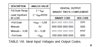
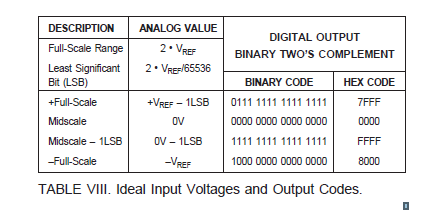
#define VREF 2.5
#define LSB_VOLTAGE (2*2.5/65536)


float convertToVoltage(uint16_t rawValue) {
    // Check if the value is in the negative range
    if (rawValue & 0x8000) {
        // Convert from 2's complement to signed integer
        int16_t signedValue = -(int16_t)(0xFFFF - rawValue + 1);
        // Calculate the voltage for the negative range
        return (float)signedValue * LSB_VOLTAGE;
    }
    else {
        // Calculate the voltage for the positive range
        return (float)rawValue * LSB_VOLTAGE;
    }
}
Here is my wirings
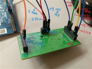
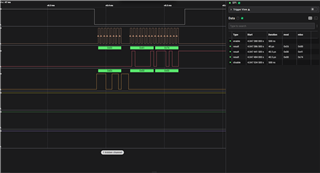
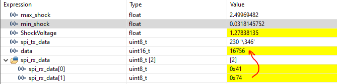
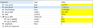
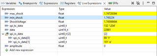
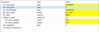
I know I am getting response from SPI but values are wrong. I measured Vref, 11.pin of IC, was 2.5V.
Could you tell me what else I can do further ?