This thread has been locked.

If you have a related question, please click the "Ask a related question" button in the top right corner. The newly created question will be automatically linked to this question.

ADS1281: How improve ADC dynamic range?

Part Number: ADS1281
Other Parts Discussed in Thread: ADS127L11

Hi to forum users!
I have a doubt about dynamic range of delta-sigma converters.
Dynamic range is based on RMS noise, higher decimation factor I use, lower RMS noise, so I try to use highest available sampling rate (Fmod) and higher decimator factor.
On datasheets I always see simple input RC lowpass filter (usually 1th order) due to high modulator frequency, this gives me low component count, low cost, low PCB space.
Regardless cost and PCB space, could I get some improvement using higher order (let's say 8th order) lowpass filter as analog anti-alias before ADC, or would it be totally worthless?
Thanks.

  • Hello Michele,

    It depends.  For low OSR values you may need a higher order anti-alias filter to maintain high levels of attenuation at the modulator frequency.

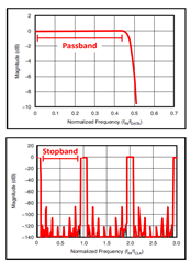
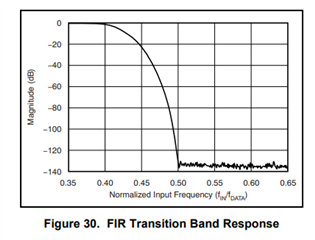
    Due to aliasing around the modulator frequency, the digital filter will no longer attenuate these signals.  Below is an example of an FIR filter at lower frequency, and the following plot shows the response at multiple integers of the modulator frequency.

    Because the digital filter has 0dB of attenuation at the modulator frequency, you must rely entirely on the analog anti-alias filter near this frequency.  For very large OSR values, the attenuation of a single order RC filter is usually enough.  For low OSR values, a 4th order or higher anti-alias analog filter may be needed.

    Using the ADS1281 as an example, one of the FIR data rates is 250sps, with a relative flat response up to 100Hz.  The modulator frequency in this case is f-CLK/4=1.024MHz.  The FIR filter above 0.5*f-DATA has an attenuation of about 130dB.

    If we want to maintain a flat frequency response out to 100Hz, then the analog filter should be set to about 10x this value, or 1000Hz.  Using a simple RC filter with a cutoff frequency of 1000Hz, the attenuation at 1.024MHz will be about -60dB.  If you are only concerned with total noise, then any noise in this frequency range will be attenuated and will not significantly add to the total noise.  However, if you are concerned about the frequency content of the noise, you could see an alias signal that is 70dB higher than the digital filter noise floor.  In this case, a 2nd order filter would have about -120dB of attenuation, and your noise floor limit is now close to the digital filter noise floor.  Increasing the analog anti-alias filter order in this example will not have much additional benefit.

    You may want to look at the TI Precision Labs - ADCs material which discusses ADC noise in more detail.

    https://www.ti.com/video/series/precision-labs/ti-precision-labs-analog-to-digital-converters-adcs.html

    Also, section 9.2 in the ADS127L11 datasheet goes through a design example for an anti-alias filter when using a lower OSR setting of 32.

    Regards,
    Keith Nicholas
    Precision ADC Applications

  • Ouch! My fault, I forget to say about my sampling rate...
    I need output sampling frequency from 100 to 200 SPS, then setting modulator frequency as I need to use largest available oversampling rate on ADS1281, so understand if for this I could get some improvement using higher order analog antia lias filter.