A related question is a question created from another question. When the related question is created, it will be automatically linked to the original question.
If you have a related question, please click the "Ask a related question" button in the top right corner. The newly created question will be automatically linked to this question.
Part Number: DAC1220 Other Parts Discussed in Thread: DAC1221,
I am curious if there are any additional, undocumented features that are using the any of the five reserved addresses? If so, is it possible to directly talk with someone about their use?
I do no think these addresses are reserved for any undocumented features, but for potential design expansion. If you look at the 16-bit version of this device, the DAC1221, there is an extra reserved location for the third DIR byte that is used in the DAC1220:
I checked in the old documentation that I could find and there was no indication that these addresses controlled other features.
Thanks. My hope was there may have been hooks for production testing. It's not something I would expect to find in a datasheet or anythingthe typical designer would have a need for. I plan on running a few tests to determine if writing random data to these locations has any effect.
One thing I noticed was Table 13, Bit 11 states Read-only. Always '0'. Table 12 Command Register shows bit 11 as a 1, not a 0. Reading two different parts, both return a 1. I recommend correcting the datasheet.
As you suggest, none of the reserved address locations appear to have any effect in the DACs operation. The same appears true for the reserved bits of the command register.
I suspect this part is doing some sort of internal zeroing. Some parts appear to behave slightly different which causes us a problem. If you have someone at TI that knows the details of how this part works, please put them in touch with me.
It may be helpful if you could share your schematic and a screenshot of the behavior shown on an oscilloscope for 2 or 3 of the parts you are having the issue with so we can look into it in more detail.
Sorry but with it being a public forum, schematics are out of the question. However, feel free to put me in contact with someone that knows the inner workings of the part ad we can certainly discuss it. An oscilloscope doesn't have near the resolution or noise floor required. I can tell you that that the problem is bad enough to cause us to reject the parts in roughly 1%.
I assume from the previous posts that your concern is that some devices have a higher offset error than others? Are you issuing calibration commands? What do you set the CALPIN function during the calibration state?
It's not an offset but a bimodal output (2-states). Manually changing the gain and offset registers appear to have no effect on the level. Nor does changing the filter. Currently I am not running any calibration or performing any communications with the device. All of the digital pins are in a fixed state during operation. The problem is something internal to the device and how it works. Guessing it is normal and possibly some sort of auto zero. Time scale is on the order of several seconds to minutes. Amplitude wise, we are talking well under 1uV.
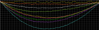
Looking at nine different DACs for a period of seven minutes. Data is normalized to help see the bimodal condition. Arc is due to drift. Note how one DAC has this bimodal condition while the others appear random as I would expect. However, I suspect all of the DACs exhibit this behavior but it is below the noise. This bimodal shift is enough to cause a problem in how we use the part. I suspect in the majority of applications it doesn't pose a problem.
I should mention that difference in the two bimodal states is below 50nV. Again, this difference changes part to part. The vast majority of them no not exhibit this condition, or at least is low enough not to cause a problem for us. Over a few thousand parts, we see around a 1% failure rate.
So this device is a current segment delta-sigma DAC. This means that we produce a higher resolution with continuous switching which allows for error-averaging. As some segments might have more error than others, you might be seeing a few devices that have more than average. This means that on some devices you might see DC error that changes over time as segments are on/off.
Can you confirm if the external oscillator is working correcting? Do you see you 2.5MHz? A slower than expected clock will reveal the segment switching.
We are using a 2.45MHz crystal for the clock. Looking at the Xout (pin2) on a bad part, it appears correct. Looking at the manual for the evaluation board, they had used a 2.4576MHz crystal.
Also note that I have gone so far as to swap DACs on two boards, one problematic to see if something else may aggravate the bimodal condition problem. The problem tracks the DAC. In my original post, I was thinking there may have been a way to command the DAC lock down it's settings. It doesn't matter that it could have this small offset but it can't be toggling between two states like it is.
While the DAC1220 might have some chopper stabilization, the clocking for the stabilization would be much smaller than the many seconds that you are seeing. Typically, you'd want chopping in the 100s of kHz range for most applications.
Also, the device doesn't have any test modes or extra undocumented features. There were some hooks to look at some settling times, but really this device is rather simple and we didn't add too much to this particular device for testing or evaluation.
Because of the multi-second to minute time scales of the bimodal output, my guess is what you are seeing is popcorn (or burst) noise. It doesn't seem to appear on all devices, and the noise is much smaller than the DAC LSB. If you're operating this on a 5V range, then 50mV is the equivalent to about 24-bits of resolution (where this DAC is a 20-bit DAC). This level of output noise is much below the resolution of the DAC and I would guess that no one would have seen it. If you've done some swapping of devices on boards, then I'm guessing that this is really the DAC1220 and not an output buffer or output filtering that is causing this problem.
To test if this is really popcorn noise, you could put a board in an oven and see if the transitions become more frequent. Heating up the device would increase the frequency of the noise, while cooling it down would give reduce the frequency of the noise.
Thanks. From my previous posts about my own testing of the reserved areas, I tend to agree that there are no usable hooks that will help mitigate this problem.
As I mentioned, I have taken a good and bad board, swapped the DAC and the problem will track the DAC. Prior while working through the problem to identify the source, I had changed the buffer to the same type and then to a different type with no effect. I am confident the problem is with the DAC.
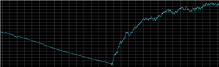
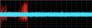
I am working in the sub uV, not mV. As you can imagine, temperature is a big deal and even small air currents can cause major problems. It could very well be RTN. The problem is even if we identify the source, I don't see how we could mitigate the problem. I have attached a photo showing the effects of exposing the system to my office air currents. Notice how it masks the bimodal problem.
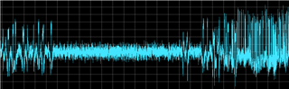
To run it in the chamber, I double insulated the electronics keep it stable enough to view the bimodal condition. I start out at room temperature then allowed the board to reach 0deg C. Next brought the board temperature to 70 deg. C. The problem does look like RTN and appears to track with temperature.
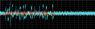
Showing a typical good DAC that was brought up to 70 deg C with all the same settings (orange) compared with the previous bad DAC (blue). Let me know if there is something else you would like to see.
With the temperature correlation, it does look like this is some sort of burst noise. I don't think we've ever seen this noise before, as this noise is much smaller than the resolution of the device.
Unfortunately, I don't really have a good way to remove this type of noise from the device. From the schematic side, chopping or autozero can reduce the apparent noise, but moving it to higher frequencies. However, I'm not sure if that's something you'd be able to do in your schematic. Your device appears to have stringent noise specifications, and I'm not sure if just moving the noise around the spectrum would work in your application.
Chopping is pretty much required to work at these levels. Agree, there is no easy fix. I assume the 1% failure rate we see is something in your process when the parts are fabricated and I am not suggesting it be addressed on your end. I doubt most of your customers would ever run into it. From TI's perspective, it sounds like the only resolution is to design out the part with the idea that we will need to do a lot more testing the next time.
Thanks for all the feedback. You may consider the matter closed.