Im attempting to ensure that I can successfully change the output voltage. My procedure is below:
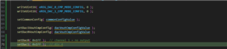
- Set the common config to 0x800
- Set dac0 and dac1 cmp config value (identically set to 0x8000)
- Set the dac output values
All writes are confirmed immediately with a readback to ensure the value has taken affect. Initially I did this with no delay and the value read back correctly.
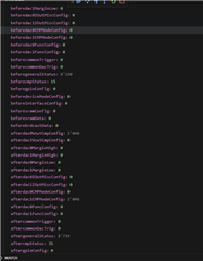
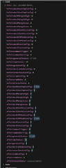
We noticed that dac0 output was working correctly but dac1 output remains at 0v on two identical boards. On interrogating the registers, we noticed that values were not being held. The below screenshot shows the registers before and after the setup I2c instructions which shows that the dac1voutcmpconfig value is not sticking, I also know from testing that the dac1data value is resetting to 0.
I implemented some defensive coding to ensure the generalStatus register shows both dac’s as ready for commands as well as a delay before the read to take into account potential resetting time. This screenshot shows the write process I am now using:
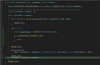
For additional information, with the defensive coding I have implemented my code now gets stuck in this loop when trying to set the dac value.
On picoscope, this results in the following odd behaviour
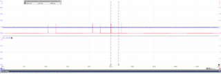
Any light anyone can shed on this behaviour is appreciated. As mentioned before we have tested this and it is identical on two boards, we also have a dev kit on the way to see if its something electronics based but Jack assures me this is unlikely.