This thread has been locked.

If you have a related question, please click the "Ask a related question" button in the top right corner. The newly created question will be automatically linked to this question.

ADS7029-Q1: SPI rise/fall time limits and specification

Part Number: ADS7029-Q1

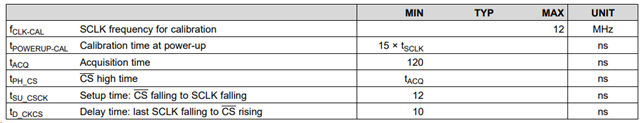
SPI timing parameters are not in the DS. When will these be documented in the datasheet?

What are the SPI clock rise/fall time min/max input requirements?

What are the SPI data input rise/fall time requirements?

What are the SPI data output rise/fall time specifications?

  • Hi Andy, 

    Thank you for your questions. I believe the information you are looking for is in sections 6.6 (timing requirements) 8.3.4 (serial interface), 8.4 (device functional modes) of the DS. Here is a screenshot some timing parameters:

    The SPI transfer frame is set by the CS signal. A frame starts with a CS falling edge and ends with a CS rising edge. There must be a minimum delay of t_SU_CSCK (12 ns) between the CS falling edge and first SCLK falling edge. The data moves on the SDO pin. The first two bits are set to 0 followed by 8 bits of the conversion data. This device only has an SDO pin, no SDI pin. The serial interface can be used to transfer the ADC conversion results to the external host. 

    Please let me know if you have any more questions.

    Best regards,

    Eva