This thread has been locked.

If you have a related question, please click the "Ask a related question" button in the top right corner. The newly created question will be automatically linked to this question.

ADS1261: ADS1261 in single-ended application

Part Number: ADS1261

Hello,

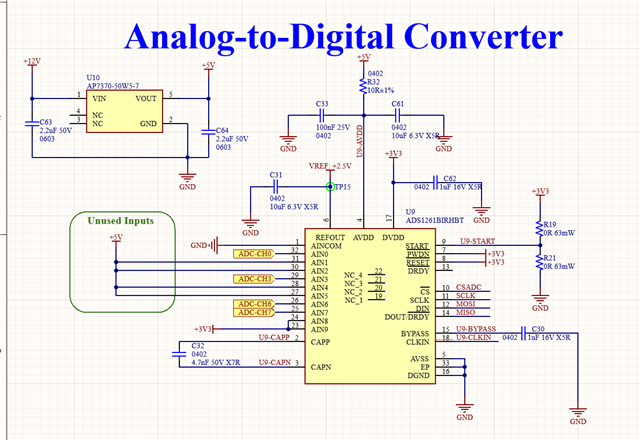
I want to implement the ADS1261 for our circuit, our purpose is to sense single-ended analog signal. 

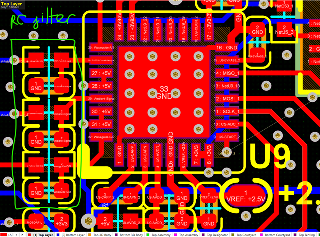
Can you help me to evaluate the schematic/layout for the IC please. 

My plan is to use the AINCOM as GND, then mux the corresponding AIN to compare the AINs with AINCOM. 

Before each input, I put a RC filter network with R=470R and C=470pF.

Thank you very much in advance.

  • Hi Takuchi,

    There is not much to review here, but it looks pretty good

    • You have a mid-supply (DVDD) voltage on the START pin. I don't know why you would do this, I would think you either want this pin pulled up or pulled down through a 10k or greater resistor since it seems like you are controlling this pin with your MCU
    • I don't see any ground connections (vias) on some of your supply decoupling and filter capacitors. Maybe you will add those later?
    • If you want to measure single-ended signals with the ADS1261, you must bypass the PGA. I just want to make sure this is clear
    • I don't see a noise specification for your linear regulator, you might consider a better LDO. We typically use the TPS7A4700 on our designs because it is low noise and has an adjustable output, but can use a similar device with a fixed output if you want
    • The resistor on AVDD (R32) will cause a voltage drop between the regulator output and the AVDD pin. In most cases, this voltage will be negligible, but there are certain circumstances where the ADC draws a lot of current for short periods of time (instantaneous current), which could cause significant voltage drop. This effect is usually most apparent at power up. There is nothing wrong with adding that resistor, but you should keep this in mind during your prototyping if you start seeing the ADC resetting or brown out conditions
    • The voltage rating on C61 (6.3V) is not very high compared to the supply voltage (5V). This could reduce the capacitance over time and temperature, especially for an X5R cap. I would consider finding a capacitor with a higher voltage rating

    -Bryan

  • Hello Bryan,

    Thank you for your answer.
    We are putting either R19 or R21 on the START pin (not both). We don't know which configuration we are using yet so I put both options there.
    Why do we have to bypass the PGA? 

  • Hi Takuchi,

    You can see from the datasheet that when the PGA is bypassed, the input signals can be referenced to ground (0 V) because AINP and AINN can be as low as AVDD - 0.1V

    However, equation 5 shows that when the PGA is enabled, even with a gain of 1 the minimum absolute input voltage on AINP or AINN must be greater than AVSS + 0.3V.

    Therefore, you cannot measure single-ended (ground-referenced) signals with the PGA enabled

    -Bryan

  • Hello Bryan,

    Thank you for your explanation, it's much clearer now.

    So if I understand it correctly. if I want to use the PGA for our single-ended signal (0 ~ 2,5V), I have to supply AVDD and AVSS with +/- 2,5V.

    Is that correct?

  • Hi Takuchi,

    If your input signal is 0-2.5V, and VREF = 2.5V, why do you need gain at all? Even if you level shifted this signal somehow the maximum gain you could possibly use is 2. And the ADS1261 is already very low noise, so maybe it will not be an issue to bypass the PGA?

    But yes, if you want to measure a single-ended (ground-referenced) input with the ADS1261 PGA enabled, you will need to use bipolar supplies

    -Bryan