This thread has been locked.

If you have a related question, please click the "Ask a related question" button in the top right corner. The newly created question will be automatically linked to this question.

ADS1298 Development - How to talk to the ADS1298 without MMB0...?

Other Parts Discussed in Thread: ADS1298, ADS1298ECGFE-PDK, ADS1198, TMS320F2812

Hi there,


So I recently purchased an ADS1298ECGFE-PDK to develop a multichannel biopotential measurement system. Unfortunately, I'm having some trouble getting the ADS1298 board to talk to the outside world, i.e. to devices other than the included MMB0 board, say, an FPGA. The MMB0 is nice, but I'd like to be able to acquire and process raw data in real time with my own hardware and software, so I need to circumvent it. 


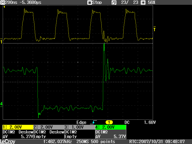
I tried connecting the SPI interface of the ADS1298 board to an Arduino as an initial experiment. The Arduino has a pretty good SPI library, so it seemed like it might be a simple way of getting raw data out of the ADS. However, in order to connect the ADS to the Arduino, I have to remove it from the MMB0 board and supply my own 5V, 3V, and 1.8V sources. I think. It's not really clear to me how to effectively power the ADS board separately from the MMB0 board. I experimentally figured out how to get those voltages to show up at the correct test points. I had the ADS board running off of voltages derived from the Arduino's power supply, which may or may not have been a good idea. When I ran a simple sketch that asked for data on the SPI interface or sent simple opcodes, I didn't see anything coming back. The START line was asserted permanently. I suspect that the ADS board is having difficulty driving the Arduino's digital inputs, but am not completely sure. Looking at the signal on a scope, it looked pretty weak. 


Basically, what I want to know is, what is the simplest configuration in which the ADS1298 demo board can be used with a third-party microcontroller (Arduino or otherwise)? What kind of supply voltages need to go where? Do I just need to use two separate power supplies, one for communications/microcontroller and one for the ADS board? Perhaps the Arduino SPI library is not to be trusted?


thanks!


  • **TI EDIT February 20th 2019; FOR GENERAL ADS129x ASSISTANCE, PLEASE SEE NEW BIOPOTENTIAL FAQ LOCATED HERE**

    Tom,

    I could see a few things potentially being incorrect here, but powering the EVM should be pretty easy. You could connect 5V to TP7, 1.8V on TP9, and 3.3V on TP10. The reference designators may be a little different on your ADS1298EVM, I only have a ADS1198 on hand, but they should be clearly marked as +5V, 1.8V, and 3.3V. The rest of the required voltages to operate the EVM will be generated by on board regulators.

    With respect to using separate power supplies for the Arduino board and the ADS1298 board, I don't see that being necessary unless your power supply cannot source enough current to drive both boards, I have no idea what the current consumption may be on your Arduino board. Do make sure that both boards are using a common ground connection though, or your SPI lines may look misleading.

    The second thing I would check is validating that your processor and the ADS1298 are operating on the same logic levels. The ADS1298EVM board supports 1.8V logic and 3.3V logic, selected through JP28. Also, you mentioned your SPI lines look "weak." You might see if there are any pad/gpio settings from within the Arduino part to increase drive strength so your SPI looks healthier.

    Third, you should take a look at the state of the RESET pin on the ADS1298. This pin is available on J3-8. The device could potentially be held in a reset state and not be communicating as a result.

    Fourth, you should be sure to comply to the power up sequence for the ADS1298 described in the ADS1298 data-sheet under the "Quick-Start Guide"

    If none of these pointers seem to drive you down the right path, please provide us with a description of your hardware set-up (all important connections, supplies, grounding, and EVM jumper settings) and perhaps some oscilloscope captures of the SPI lines you've got right now.

    We also have an FAQ section about the ADS1298 in our design notes section which you can view here:

    http://e2e.ti.com/support/data_converters/precision_data_converters/w/design_notes/frequently-asked-ads1298-and-ads1198-questions.aspx

    There is also a forum thread about this topic you can view here:

    http://e2e.ti.com/support/data_converters/precision_data_converters/f/73/p/105352/372323.aspx#372323

    There's been a lot of community activity here about the ADS1298 and ADS1198, so you may also find other resources via the search tool.

  • Hi Kevin, I am using ads1298ecgfe board without mmb0. I am connecting the ads1298 board with a tms320f2812. My question is the following. The logic high level output of my dsp is 3.6v and maximum logic high level of my ads1298 is dvdd+0.1. So dvdd of my ads1298 it has to be 3.5v. I can use this voltage in ads1298ecgfe board?

    Thanks a lot.

  • Oscar,

    3.6 V should be fine to apply to the ADS1298ECGFE board, most of the board uses the 5V plane anyhow.

  • Hi, Kevin thanks for your response.

    So, my voltage supply are the following connect 5V to TP7, 1.8V on TP9, and 3.5v on TP10.

    Is that right?

  • Oscar,

    It wouldn't be necessary to supply 1.8V on TP9. TP9 and TP10 are test points directly from the power connector at J4, both are then routed to JP28 where the user of the EVM-PDK may choose 1.8V or 3.3V to supply DVDD for the system. You could just supply 3.5V on TP10 with JP28 in the 2-3 position or you could apply the 3.5V directly to the center pin of JP28.

  • Thanks Kevin for your responds. Kevin I have another question. Output tms320f2812 signal has an overshoot of 3.8v, I want to know if that voltage can damage my ads1298ecgfe?


    If that is truth I have to include other hardware part that  convert those overshoots, you recommend  me some shifter voltage level?

  • Hi Oscar,

    I assume these are overshoots that you have observed with an oscilloscope? I didn't see any mention of an overshoot in the TMS320F2812 datasheet, I could have missed it though. If you have observed this overshoot please share with us some screen shots. If it looks something like glitch, like the figure below, you could probably get rid of the 3.8V spike just by adding some series resistance or capacitance to terminate the transmission line and smooth out the impulse.

    An overshoot or glitch like the one shown in the figure below can also sometimes be an artifact of measurement techniques, so it may not be real. You would need to improve your measurement techniques to confirm whether its an artifact or not however. You could use a shorter ground strap on your scope probe and try to get a ground plane connection as close to the pin as possible.

    Alternatively, if the overshoot you've observed or read about is a sustained 3.8V across the entire transmission of the logical high you would probably need to add a logic shifter. Usually you can wiggle a few millivolts around an absolute maximum spec, but I can't guarantee it would not damage the device across multiple lots / ICs since you'd be right at the absolute maximum. I would be very surprised if this were the case though...

    I've included a presentation from a past Tech Day that talks about transmission line termination.

    7433.pa-113_transmissionlines.ppt

  • Kevin I really apreciate your help, Yes i have some glitch, I use a buffer to limit voltage but the input is a little faster than my output.+

    Buffer power  supply are 3.3v (+) and 0v (-). That limit my voltage to maximum 3.3v. 

    Vi= Output TMS320F2812.

    Vo= 3.3v or 0v.

    What do u think about that solution? 

    Kevin where can i buy the cable that appear on datasheet because the webpage that suggest me, doesn't respond.

    Page 59.

    10-lead ECG cable for Philips/HP-snap, button (Part No: 010302013);

    http://www.biometriccables.com/index.php?productID=692 10-lead ECG cable for Philips/HP-Clip-on type (Part No: 010303013A);

    http://www.biometriccables.com/index.php?productID=693

    Thanks again. 


  • Oscar,

    I don't see anything wrong with using an op amp as you've described, except that it is sort of a waste of an op amp, power, and space where a simpler termination technique would probably work just as well. A level shifter would probably be best suited if you do not want to terminate the line with a resistor or resistor/capacitor combination.

    I'm not sure why those links don't work for you. On my end it takes me directly to the relevant products on the biometric cables website. If you visit http://www.biometriccables.com/ you can navigate manually to the products. From the main page click on "Texas Instruments modules(TI)" and you should be able to see all of the products that you're looking for. I don't think biometric cables has a real "online store" so you have to email them to request any product. I'm not sure which email is correct for ordering a product but you can try customercare@biometriccables.com or info@biometriccables.com (I think info is the appropriate one for ordering products) if you can't get to the website.

  • Hi Kevin thanks for your answer, Kevin I need your help again, do you have any scheme of resistor capacitor circuito to above that overshoot that I mention before.

    thanks a lot.

  • Oscar,

    You might start by just adding a ~33 Ohm resistor in series between the uC and ADC. That will at least reduce the magnitude of the overshoot you're seeing such that it shouldn't be a problem. If that's not enough you can add a ~10pF capacitor to ground after the resistor to filter and round out the edges of your signals. If you really want to tailor the solution to your specific situation, you can try finding the frequency of the overshoot and create this RC filter to specifically eliminate that frequency.

  • Hi kevin.

    I have a question what kind of digital notch filter use the ads1298ecgfe, and Can I find the code of that program? Is an open project?


    Thanks a lot.

  • Hi Oscar,

    Generally all of the hardware and software in our evaluation systems is open source, with a few exceptions like the Opal Kelly platform. You're free to look at and and utilize code resident on the DSP and PC, so long as any of the items that you choose to reuse that fall under GPL are utilized appropriately. The digital notch filters used in the ADS1298 EVM are implemented in LabVIEW, it just makes the most sense given our set-up to offload some of these more processing intensive tasks to the PC since it's available. The LabVIEW code is a direct implementation of some C code one of our MCU teams provided. I've attached that code to this post and you may do as you wish with it. If you would prefer the LabVIEW source, please let me know and I can provide that as well.

    It is of note, however, that this source is provided as is and we do not provide extensive support for the modification or re-implementation of any source provided. Sort of "here it is, good luck, have fun." Additionally, digital filtering algorithms must be tuned to some sampling frequency in order to accurately filter the signal, this code is tuned for 500sps. If you wish to do digital filtering at a different sampling frequency you will have to change this code.


    Here it is, good luck, have fun!

    6378.dsp_notch_filter.c
    /* notch filter, rejecting 60Hz powerline signal, consists of a cascade of two 2nd-order IIR filters (notch1/notch2) */
    
    int notch1out,dly_notch1[3]={0};
    void notch1 (int input)
    { 
    	int node[12];
    	node[0]=0;
    	node[1]=0;
    	node[2]=0; 
    	node[3]=input;
    	node[6]=input - dly_notch1[1];
    	node[7]=node[6] - (node[6]>>5);
    	node[8]=node[7]  + input;
    	node[9]=node[8]  - dly_notch1[2];
    	node[10]=0-((node[9]+(node[9]>>1)-((node[9]+(node[9]>>1))>>5)+((node[9]+((node[9]+(node[9]>>2))>>2))>>8))>>1);
    	node[11]=node[8] + node[10];
    	node[5]=node[10] + dly_notch1[2];
    	node[4]=node[7]  + dly_notch1[1];
    	notch1out=(node[4] + node[3])>>1; dly_notch1[0]=node[0]; dly_notch1[1]=node[5]; dly_notch1[2]=node[11]; 
    }
    
    int notch2out,dly_notch2[3]={0};
    void notch2 (int input)
    {
    	int node[12];
    	node[0]=0;
    	node[1]=0;
    	node[2]=0; 
    	node[3]=input;
    	node[6]=input - dly_notch2[1];
    	node[7]=node[6] - (node[6]>>5);
    	node[8]=node[7]  + input;
    	node[9]=node[8]  - dly_notch2[2];
       	node[10]=0-((node[9]+(node[9]>>1)-((node[9]+(node[9]>>1))>>5)+((node[9]+(node[9]>>3))>>8))>>1);
       	node[11]=node[8] + node[10];
       	node[5]=node[10] + dly_notch2[2];
       	node[4]=node[7]  + dly_notch2[1];
       	notch2out=(node[4] + node[3])>>1; dly_notch2[0]=node[0]; dly_notch2[1]=node[5]; dly_notch2[2]=node[11]; 
    }
    
    
    /* notch filter, rejecting 50Hz powerline signal, consists of a cascade of two 2nd-order IIR filters (notcha/notchb) */
    
    int notchaout,dly_notcha[3]={0};
    void notcha (int input)
    {
    	int node[12];
    	node[0]=0;
    	node[1]=0;
    	node[2]=0; 
    	node[3]=input;
    	node[6]=input - dly_notcha[1];
    	node[7]=node[6] - (node[6]>>5);
       	node[8]=node[7]  + input;
       	node[9]=node[8]  - dly_notcha[2];
       	node[10]=0-((node[9]+((node[9]+((node[9]-((node[9]-((node[9]+(node[9]>>2))>>3))>>4))>>2))>>1))>>1);
       	node[11]=node[8] + node[10];
       	node[5]=node[10] + dly_notcha[2];
       	node[4]=node[7]  + dly_notcha[1];
       	notchaout=(node[4] + node[3])>>1; dly_notcha[0]=node[0]; dly_notcha[1]=node[5]; dly_notcha[2]=node[11]; 
    }
    
    int notchbout,dly_notchb[3]={0};
    void notchb (int input)
    { 
    	int node[12];
    	node[0]=0; node[1]=0; node[2]=0; 
    	node[3]=input;
    	node[6]=input - dly_notchb[1];
    	node[7]=node[6] - (node[6]>>5);
    	node[8]=node[7]  + input;
    	node[9]=node[8]  - dly_notchb[2];
    	node[10]=0-((node[9]+((node[9]+((node[9]-((node[9]-(node[9]>>4))>>4))>>2))>>1))>>1);
    	node[11]=node[8] + node[10];
    	node[5]=node[10] + dly_notchb[2];
    	node[4]=node[7]  + dly_notchb[1];
    	notchbout=(node[4] + node[3])>>1; dly_notchb[0]=node[0]; dly_notchb[1]=node[5]; dly_notchb[2]=node[11]; 
    }


  • Thanks Kevin, this is the filter that use ads1298ecgfe, consists of a cascade of two 2nd-order IIR filters.

    Kevin I really apreciate your help if you can send me the c code of ads1298ecgfe software.

    You are right, the only way that i can use notch filter is 500sps configuration, i want to try with other sample rate.

    thanks again. 

  • Kevin sorry, Another question how can i get the values of my ecg signal, for matlab processing.

  • Oscar,

    I can dig up the source for that if you would like, but I should let you know that there is no filtering on the DSP in the EVM. As I mentioned, the filtering exclusively happens on the LabVIEW side. If the source is still of interest to you, let me know and I'll find it.

  • Oscar,

    Attached to this post is the ADS1298 firmware source.

    As for your other question, there is an option to save the data from the ADS1298 LabVIEW software under the "Save" tab. You can see this on page 20 of the EVM User's Guide. The output file is tab delimited, so if matlab doesn't have a convenient way built in to import data from a tab delimited file it shouldn't be too hard to write your own script with some pretty basic regular expressions to grab the data.

    3288.Source_FW_ADS1298.zip

  • HI Kevin, I am programing my ads1298ecgfe with tms320f2812 but i can acquire data.

    This is my registers configuration.

    Pin configuration:

    Clksel=1; for use an internal socillator

    Reset =1;

    Pwdn=1;

    Start=0; for use opcode

    CS= 0; all the time.

    SPCLK=780Khz.

    Cpol=0;

    Cphase=1;

    All pins have this configuration when i turn on the device.

    The following is my registers configuration via spi


    //Spi commando configuration


     SpiaRegs.SPITXBUF=0x0600; //RESET


     // wait 18tclk for another command

        SpiaRegs.SPITXBUF=0x1100;

      //Here I have to wait?? Using 780khz??

        SpiaRegs.SPITXBUF=0x4300;//CONFIG3
        SpiaRegs.SPITXBUF=0xE000; //
        delay_loop();
        delay_loop(); //wait for internal reference
        delay_loop();
        delay_loop();
        delay_loop();
        delay_loop();
        delay_loop();
        delay_loop();
        delay_loop();
        delay_loop();
        delay_loop();


        ///CONFIG1
        //HR DAISY_EN CLK_EN 0 0 DR2 DR1 DR0
        SpiaRegs.SPITXBUF=0x4100; //
        SpiaRegs.SPITXBUF=0xA600; // config1


        //CONFIG2
        //0 0 0 INT_TEST 0 TEST_AMP TEST_FREQ1 TEST_FRED0 
        SpiaRegs.SPITXBUF=0x4200; // config2
        SpiaRegs.SPITXBUF=0x1000; // config2


        //CONFIG CHnSET
        //PD1 GAIN12 GAIN11 GAIN10 0 MUXn2 MUXn1 MUXn0
        //TEST SIGNAL CONFIGURATION
        SpiaRegs.SPITXBUF=0x4500; // CH1
        SpiaRegs.SPITXBUF=0x0500; //
        SpiaRegs.SPITXBUF=0x4600; // CH2
        SpiaRegs.SPITXBUF=0x0500; //
        SpiaRegs.SPITXBUF=0x4700; // CH3
        SpiaRegs.SPITXBUF=0x0500; //
        SpiaRegs.SPITXBUF=0x4800; // CH4
        SpiaRegs.SPITXBUF=0x0500; //
        SpiaRegs.SPITXBUF=0x4900; // CH5
        SpiaRegs.SPITXBUF=0x0500; //
        SpiaRegs.SPITXBUF=0x4A00; // CH6
        SpiaRegs.SPITXBUF=0x0500; //
        SpiaRegs.SPITXBUF=0x4B00; // CH7
        SpiaRegs.SPITXBUF=0x0500; // 
        SpiaRegs.SPITXBUF=0x4C00; // CH8
        SpiaRegs.SPITXBUF=0x0500; // 


       SpiaRegs.SPITXBUF=0x0800; // START


        SpiaRegs.SPITXBUF=0x1000; // RDATAC


      Maybe I have timing configuration problem, Please tell me  how many tclk or time i have to wait between command?

    I want to know if I use that freq sclk I have to wait something, please look at page 42  version SBAS459H –JANUARY 2010–REVISED MAY 2011,  topic

    Sending Multi-Byte Commands.


    Thanks Again, Ads1298ecgfe it´s working well wiht mmb0.


  • Hi Kevin,


    Can you provide the unzipping password for the "3288.Source_FW_ADS1298.zip" file?

    Thank you very much.


    Francois

  • Hi Kevin How are you?  Kevin i can acquire signals using ads1298 - tms320f2812, right now i am using test signal configuration and i have some problem.

    The value that i acquire from my project it is not the same that appear in ads1298ecgfe program.

    The  register configuration is ok.

    If you can send me, the output values of all channel in test mode configuration I really aprecite your help.

    Thanks Again.


  • Tom I have another problem, I think is the real problem, I can acquire some signal from my ads1298 but i can see drdy signals, it is always in high statte here is a picture of my spclk and drdy signal.

    Its correct spclk cpol=0 and cphase=1


  • Oscar,

    Here is a screenshot of the ADS1298ECG-FE board outputting the test signal at 1kSPS in a gain of 12.You will notice that the offset varies slightly from channel to channel.

    Regards,

    Tony Calabria


  • Thanks Tom, I havethat program and I can see that wave form because i have ads1298ecgfe kit. I f ou can send me the hex format of those square wave.

    IMPORTANT: I can´t see drdy toggle, drdy signals is always 1.  it doesn´t change, but i can see some values ondout pin

    Thanks again