This thread has been locked.

If you have a related question, please click the "Ask a related question" button in the top right corner. The newly created question will be automatically linked to this question.

ADC12DJ5200RF: I want to connect multiple devices and use them with time interleaving.

Part Number: ADC12DJ5200RF
Other Parts Discussed in Thread: ADC08DJ5200RF, , ADC12DJ4000RF, LMX1204, LMX2582

Dear, TI support team.

I have a question about the ADC08DJ5200RF or ADC12DJ5200RF.
One of our customers requires measurement equipment to sample between 50Gsps and 100Gsps.
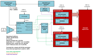
We are proposing to increase the sampling rate by connecting the fastest sampling A/D converters, ADC08DJ5200RF and ADC12DJ5200RF, in parallel.

However, neither we nor the customer have the know-how on time-interleaved connections,
so we would like to receive advice on how to synchronize the clock and avoid spurious errors such as jitter, offset, and gain errors.

The clock is generated from Vertex FPGA and uses JSED204B/C.
By the way, ADC12DJ4000RF is not listed in the overview, will it be discontinued?
https://www.ti.com/data-converters/adc-circuit/high-speed/overview.html

Best Regards,
HIroaki Yuyama

  • nHello Hiroaki,

    This is very doable and the ADC12DJ5200rf family has some built in features to make this easier to accomplish. The easiest way to do this would be the following...

    First you have to synchronize multiple ADC12DJ5200 devices, meaning they need the same device clock and sysref signals. For this I would recommend using the LMX1204 part, it is very useful for accomplishing this goal. The way the lmx1204 works is you apply a reference clock in and it will divide it out to 4 clock outputs along with sysref, so this allows getting 4 clocks to multiple parts very simple. It is important however to length match these traces/cables as the clock signals will be quite fast. See the block diagram I have attached below that shows the setup for synchronizing multiple ADC12DJ5200rf EVMs. This just shows the setup for synchronizing two evms but this can be replicated to synchronize as many as you would like.

    Once you have this setup working and all the evms are synchronized the ADC12DJ5200 has a feature called TAD which can actually be used to adjust the sampling instance of the ADC clock, this feature is available through the ADC's register writes. Using this feature you can move the sampling instance of the ADCs around and this will allow you to easier interleave the ADCs.

    From what you say in the setup above it sounds like you will run into an interesting problem as your going to have to interleave more than 4 ADCs to achieve the effective sampling rates your looking for, so you will have to use multiple lmx1204 that all must be synchronized. Additionally you will also need multiple FPGAs to capture all of this data.

    One other comment, I would not recommend using an FPGA clock to clock the ADCs this will provide very very poor performance. Instead if you need a clocking source I would recommend the lmx2582 part which is an rf clock synthesizer.

    Best,

    Eric Kleckner