


Other Parts Discussed in Thread: AMC1035, ISO7740, DS90LV027A, DS90LV028A, AMC1210, AMC1336
Hello,
in the datasheet of AMC1035 is written: "The modulator bitstream on the DOUT pin changes with the rising edge of the clock signal applied on the CLKIN pin. Use the rising edge of the clock to latch the modulator bitstream at the input of the digital filter device."
Why is it recommended to use the rising edge for latching the input data? The AMC1035 defines a minimum hold time tH1 of 6 ns and a maximum setup time tD1 of 25 ns (no manchester coding). If no other mismatch is inserted, the I would expect to use falling edge to read in the data, but the maximum setup time is very long with half period of 20 MHz, which would ideally be the falling edge moment.
For an isolated measurement I'm planning the following setup: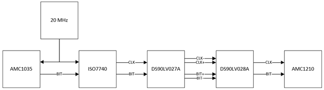
The ISO7740 is defined with a Channel-to-channel output skew time for Same-direction channels of maximum 4.1 ns.
The DS90LV027A is defined with a Channel to Channel Skew of maximum 0.8 ns.
The DS90LV028A is defined with a Differential Channel-to-Channel Skew-same device of maximum 0.5 ns
Therefore in sum a resulting timing mismatch between clock and data can be up to +/- 5.4 ns.
The AMC1210 requires a setup time before the rising edge of minimum 5 ns and a hold time after rising edge of minimum 5 ns.
If the minimum hold time of the AMC1035 was at least 5.4 ns + 5 ns = 10.4 ns, the the AMC1210 could work on rising edge.
If the maximum setup time of the AMC1035 was less than 25 ns - 5.4 ns - 5 ns = 14.6 ns, then the AMC1210 could work on falling edge.
So again the question: Can the AMC1035 setup time really be up to 25 ns? It seems to be such a large value.
Thanks,
Chris
