This thread has been locked.

If you have a related question, please click the "Ask a related question" button in the top right corner. The newly created question will be automatically linked to this question.

ADS1120: ADS1120 is used in one of our circuit to read -10V to 25mV with excitation voltage of 10V

Part Number: ADS1120
Other Parts Discussed in Thread: INA823

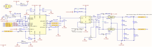
Below circuit used for reading the mV input voltage from sensor with excitation voltage of 10V. Need some technical review is this circuit meet our expectation.

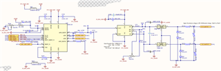
kindly review and let me your suggestions.\

Thank you

  • Hi Balakrishna DE,

    Can you please send a higher resolution image, the one you have included is blurry and therefore hard to read.

    Please double check after you reply that your image / post is readable.

    -Bryan

  • Hi, good resolution image is attached here.

  • Hi Balakrishna DE,

    Thanks for providing good resolution image, will take a closer look and provide comments by tomorrow.

    Best Regards,

    Angel

  • Apologies for the delay, will review by the end of the week.

  • Hi Balakrishna DE,

    I think it would be very helpful for you to review A Basic Guide to Bridge Measurements.  This document will explain a number of the issues with making these types of measurements.  For example the importance of limiting excitation drift by making the measurement ratiometric where the excitation for the bridge and the ADC reference are the same.  The following are some of the potential issues with your schematic:

    • If the bridge excitation is 10V, the common-mode voltage is 5V but the INA823 is powered by 3.3V.
    • The INA output is relative to ground, but the input is +/- so you cannot measure a negative going signal as the lowest the output can go is 0V.
    • You are using trim pots that usually have considerable drift which will affect the accuracy of the measurements.
    • The use of ferrites in the supply can be problematic as the ADC may require fast and large current demands due to switching transients and the ferrites may limit the required current.
    • Ferrites between the analog and digital grounds are for sure an issue.  Replace the ferrite with a 0 ohm resistor as the potential between AVSS and DGND should be the same voltage for unipolar supplies.
    • DRDY is shorted to ground through R270.  DRDY is a push-pull always active output pin and the short will cause an issue. Remove R270.

    These are some of the major issues.  Reviewing the guide I mentioned earlier should help answer some of the design questions.

    Best regards,

    Bob B