DAC7562: DAC-A and DAC-B output at the same time

Part Number: DAC7562

Hi,

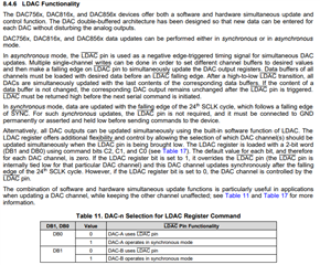
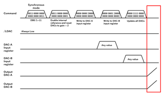
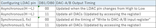
My customer usage is synchronous mode, using internal reference power, output gain=2.

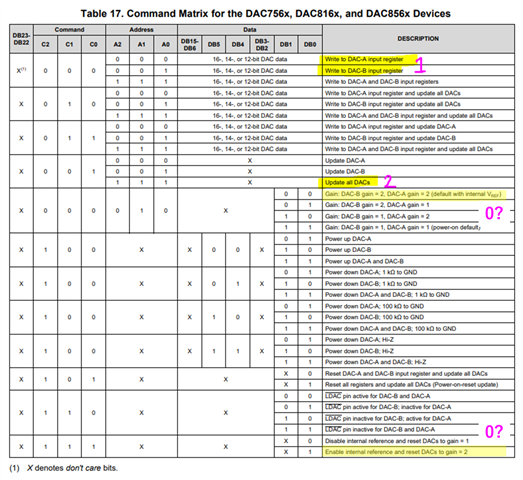
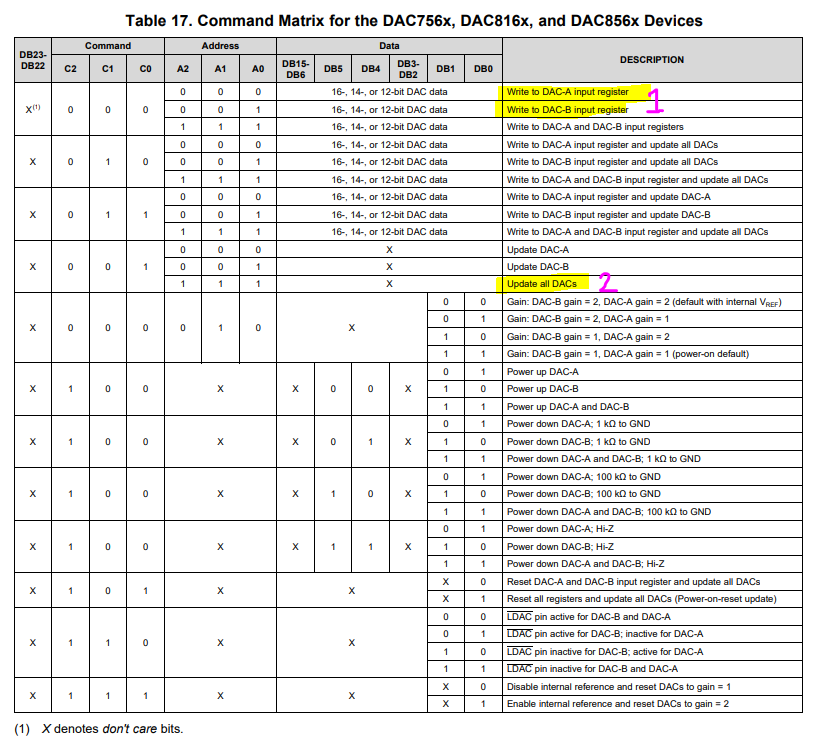
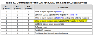
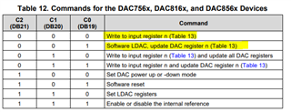
Customer want to write values to DAC-A and DAC-B respectively and output them at the same time. Please tell me how to send a command.

Best Regards,

Nishie

  • Hi Nishie-san, 

    This depends if you want to use a hardware trigger or software trigger to update the channels.

    For the hardware trigger you need to enable the DAC channels to respond to the LDAC pin which is the default operation. This is set in DB0 and DB1.

    For software trigger, set DB0 and DB1 to 1 and keep the LDAC pin always pulled low. Use the highlighted commands to first update the input registers to the desired code for each channel, and then the update all DACs command to update the two out

    Best,

    Katlynne Jones

  • Hi Katlynne-san,

    Thank you for your reply.

    Because I use the software trigger, I will set DB0 and DB1to1 and keep the LDAC pin always pulled low.

    1) When should I set Enable internal reference and Gain=2? (No.0 in following figure?)

    2) Also, Which I use "Gain: DAC-B gain=2, DAC-A gain=2 (default with internal VREF)" or "Enable internal reference and reset DACs to gain=2"?

    Best Regards,

    Nishie

  • Hi Nishie-san, 

    The gain = 2 option is set by default when the internal reference is powered on, so you do not need to write this command. You would only need to write that command if you were using an external reference and wanted to use the gain = 2 option. 

    Just write the "Enable internal reference and Gain=2" as the first command on startup. Then use the  commands 1 & 2 to write to the input registers and update the outputs as needed. 

    Best,

    Katlynne Jones

  • Hi Katlynne-san,

    I have two questions.

    <Question 1>

    I asked the customer to check the operation, but DAC-A will output when the number is 3 in the following procedure. Could you please check if there is a mistake in the procedure?

    <Procedure>

    1) / Always pull down LDAC and send commands DB0, DB1=1.

    2) DAC internal reference Send commands to enable power and double output gain.

    3) Write to DAC-A input register (No. 1 in the figure below).

    <Question 2>

    The datasheet states, "When in Synchronous mode (/LDAC=Low), data are updated with the falling edge of the 24th SCLK cycle." I interpreted this sentence as, "In Synchronous mode, a write command to the input register outputs data from the DAC."

    If I use two-step writing like that set the LDAC Register to DB1/DB0=1/1 and write to the Input register (C-2-C0=000) → write to the Update Register (C2-C0=001, etc.), is it possible to simultaneously output DAC-A/B?

    Best Regards,

    Nishie

  • Hi Nishie-san, 

    <Question 1>

    1. 0011 0000 0000 0000 0000 0011, LDAC pin inactive for DAC-B and DAC-A

    2. 0011 1000 0000 0000 0000 0001, Enable internal reference and reset DACs to gain = 2

    3. 0000 0000 [0000 0000 0000 0000], Update channel A input register with data in [ ]

    4. 0000 0001 [0000 0000 0000 0000], Update channel B input register with data in [ }

    5. 0000 1111 0000 0000 0000 0000, Update DAC A and B outputs

    Can you confirm they are using the above sequence and their codes match the ones I shared?

     <Question 2>

    The external hardware LDAC is typically used if there is some external stimulus that should cause the DAC outputs to change. It is much faster than writing an update with software. The command takes effect when the LDAC is pulled low. This means the command (to set and update the DAC outputs) can be written much earlier, but won't take effect until the external LDAC is pulled low. 

    In synchronous mode the command will take effect on the 24th SCLK. So the command will take effect as soon as it is written to the DAC. If you want the outputs to update simultaneously, this mode requires you to write to the input register and then update the DAC registers) The "Update all DACs" command is effectively a software LDAC. 

    Best,

    Katlynne 

  • Hi Katlynne-san,

    I would like to share the waveform measured by the customer with you in a private message. Can I apply for a friend?

    Best Regards,

    Nishie

  • Hi Nishie-san,

    Katlynne is currently out of office. She will return on Monday to assist you.

    Thank you,
    Erin

  • Hi Erin-san,

    Thank you for the information.

    Hi Katlynne-san,

    I have additional questions. I would appreciate it if you could answer and apply for a friend.

    Because the number of accesses decrease, the customer took the following sequence to write:

    1. 1111 0111 1111 1111 1111 1111 nLDAC pin inactive for DAC-B and DAC-A
    2. 1111 1111 1111 1111 1111 1111 Enable internal reference and reset DACs to gain=2
    3. 1100 0000 [xxxx xxxx xxxx xxxx] Write to DAC-A input register
    4. 1101 0001 [xxxx xxxx xxxx xxxx] Write to DAC-B input register and update all DACs

    *The indeterminate part is performed with 1 instead of 0. The connection of nLDACpin is fixed to Low because it is connected to GND.

    It is different from the procedure you told me, but is there any difference in the operation? (I understand that "Write to DAC-B input register and all update DACs" and "Update all DACs" are same, is it actually different?)

    In the customer sequence, only DAC-A was printed in the third step.

    Best Regards,

    Nishie

  • Hi Nishie-san,

    It is different from the procedure you told me, but is there any difference in the operation? (I understand that "Write to DAC-B input register and all update DACs" and "Update all DACs" are same, is it actually different?)

    These two commands should both move data from DAC A/B to the outputs of DAC A/B. The "Write to DAC-B input register and all update DACs" will update the data in the DAC B register before updating the DAC B output. 

    In the customer sequence, only DAC-A was printed in the third step.

    Do you mean that the DAC A output changed after the third step?

    The shorter sequence that the customer is doing should work the same as the one I shared before. They are combining steps 4 & 5 from my procedure into two steps which should operate the same. 

    Best,

    Katlynne Jones

  • Hi Katlynne-san,

    Thank you for your friend request and reply.

    I understand that there is no difference in the end result between the customer sequence and the Katlynne-san's sequence.

    I also sent the waveform in a private message. If there is a solution to output DAC-A and DAC-B at the same time, please let me know.

    Best Regards,

    Nishie

  • Hi Nishie-san,

    I am confident the settings are correct and the scope shots look correct. I've ordered an EVM so I can try to test myself in the lab. 

    If the customer also wants to send a scope shot to verify commands 1 and 2 then I can look at those as well while I wait for the EVM. 

    Best,

    Katlynne Jones

  • Hi Katlynne-san,

    I am confident the settings are correct and the scope shots look correct.

    Customer don't want behavior like a waveform. The diagram attached to the private message shows the waveforms when "Write to DAC-A input register" is executed. The customer wants to execute "Write to DAC-A input register" but not output from DAC-A. Is the procedure you told me different from the customer's desired behavior?

    If the customer also wants to send a scope shot to verify commands 1 and 2 then I can look at those as well while I wait for the EVM. 

    I would like you to measure the waveform by all means.

    Best Regards,

    Nishie

  • Hi Nishie-san,

    I mean that the waveform looks correct as far as the SPI command being sent, but I do not think the output should be updated like is shown later in the waveform. I will check on the EVM and verify the behavior when it arrives. 

    Best,

    Katlynne 

  • Hi Katlynne-san,

    Thank you for your support.

    I drew a diagram based on the procedure you told me. The behavior the customer wants to do is the red frame shown below.

    I would appreciate it if you could check if EVM can do the same.

    Best Regards,

    Nishie

  • Hi Nishie-san,

    That is the behavior I expect the procedure we discussed to give. Both the original one I sent and the modified one from the customer. But let me test on the EVM when it arrives to verify. 

    Best,

    Katlynne Jones

  • Hi Katlynne-san,

    Thank you for considering conducting the test.

    I have additional questions.

    I understand that synchronous/asynchronous settings are determined by HW or SW (register settings). When setting with HW (LDAC pin) and SW (DB1/DB0) as shown in the table below, is the output timing of DAC-A/B correct according to the information provided?

    Best Regards,

    Nishie

  • Hi Nishie-san,

    I should have the test results by Monday to verify the commands needed to update DAC A & B at the same time. 

    Are you asking me to test each combination of DB0 & DB1 in this table to verify that it is accurate?

    Best,

    Katlynne 

  • Hi Katlynne-san,

    I should have the test results by Monday to verify the commands needed to update DAC A & B at the same time. 

    ->Thank you for your support.

    I look forward to the test results.

    Are you asking me to test each combination of DB0 & DB1 in this table to verify that it is accurate?

    ->No. I apologize for the lack of explanation.

    I would like to check if the four types I described are correct for the DAC-A/B output timing control method.

    Best Regards,

    Nishie

  • Hi Nishie-san,

    I found the issue with the procedure. The LDAC pin should be externally held high, not low. In this case, the command to write to the input registers does not update the outputs as it is waiting for the LDAC pulse. The update all DACs command acts as the SW LDAC to update the outputs without needing to change the state of the LDAC pin via hardware. 

    The procedure should be updated to:

    Keep LDAC pin always pulled high

    1. 0011 1000 0000 0000 0000 0001, Enable internal reference and reset DACs to gain = 2
    2. 0000 0000 [0000 0000 0000 0000], Update channel A input register with data in [ ]
    3. 0000 0001 [0000 0000 0000 0000], Update channel B input register with data in [ ]
    4. 0000 1111 0000 0000 0000 0000, Update DAC A and B outputs

    Or the shorter version from the customer:

    Keep LDAC pin always pulled high

    1. 1111 1111 1111 1111 1111 1111 Enable internal reference and reset DACs to gain=2
    2. 1100 0000 [xxxx xxxx xxxx xxxx] Write to DAC-A input register
    3. 1101 0001 [xxxx xxxx xxxx xxxx] Write to DAC-B input register and update all DACs

    I confirmed both of these procedures on the EVM. 

    DB0/1 in the LDAC register determines if the LDAC pin is functional, or internally grounded. If the LDAC pin is grounded either externally or internally with DB0/1 then the device will always work in synchronous mode and the "write to DACx input register" will immediately update the DAC outputs. 

    Best,

    Katlynne Jones

  • Hi Katlynne-san,

    Thank you for confirming. Your support is really helpful.

    I will fix LDAC to High and try using the procedure you gave me.

    Best Regards,

    Nishie

  • Hi Nishie-san,

    Please let me know if you run into any trouble. 

    Best,

    Katlynne