DAC8742H: UART Communication in DAC8742HEVM

Part Number: DAC8742H

Dear TI Technical Support,

Currently we are developing instrument device with Foundation Fieldbus H1 protocol.

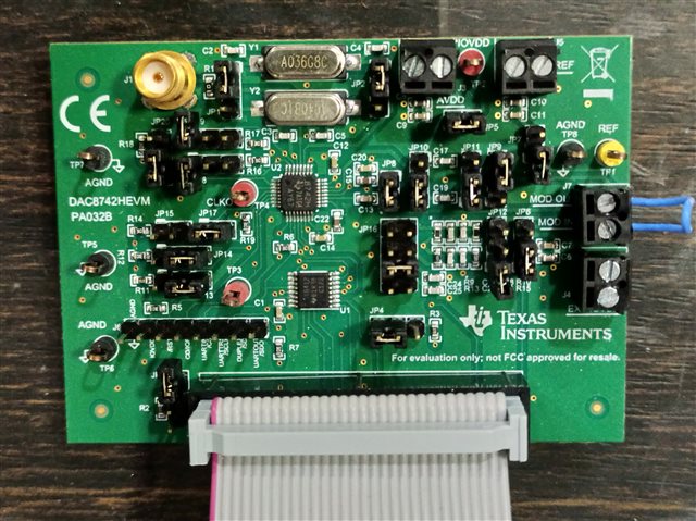
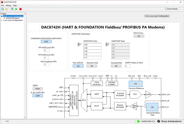
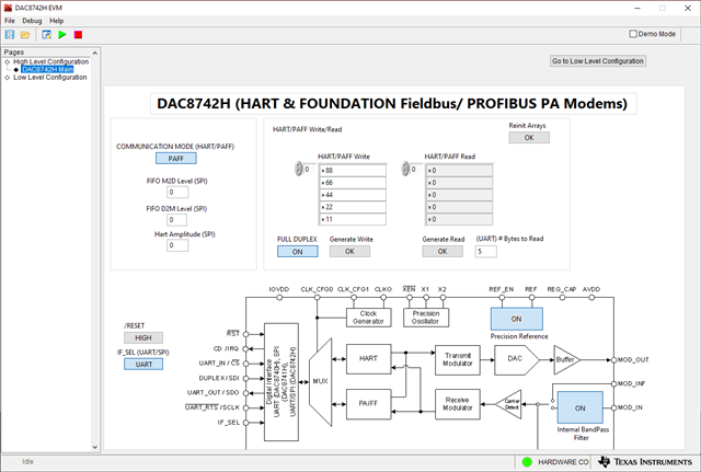
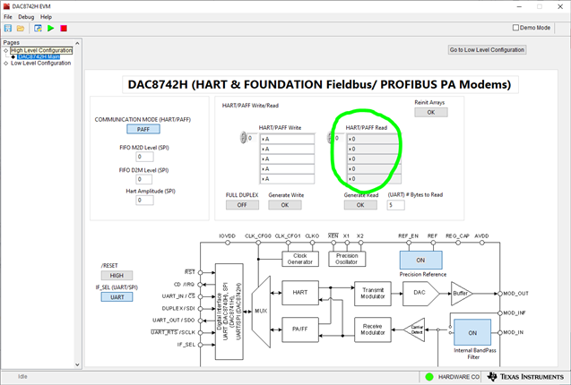
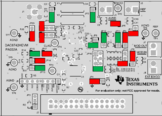
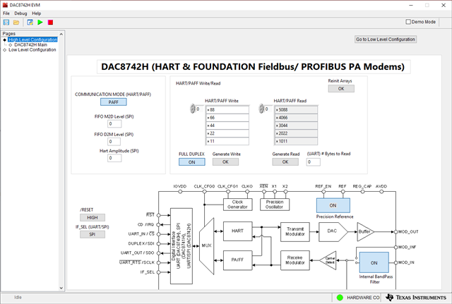
I have DAC8742HEVM Development Kit and I try to test the kit using DAC8742HEVM GUI Software.

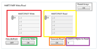
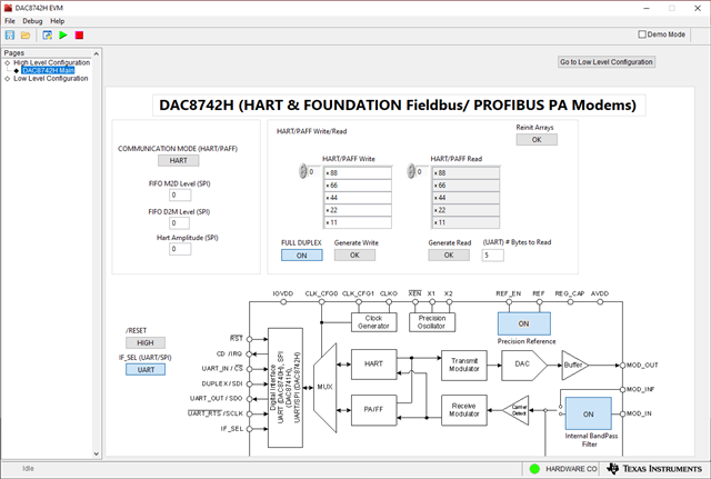
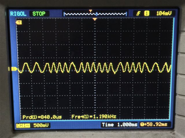
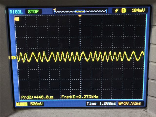
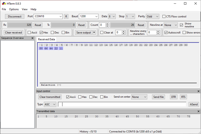
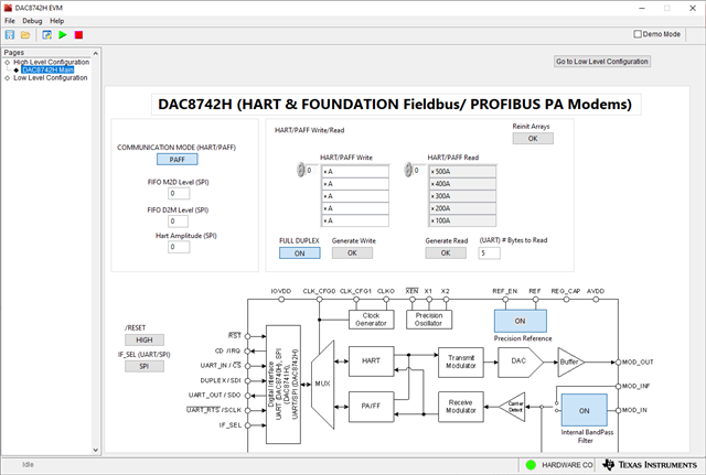
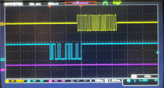
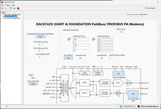
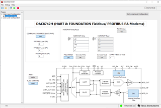
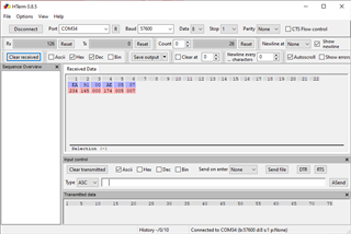
In that software I already can send and receive some data in SPI Mode for HART and PAFF communication.

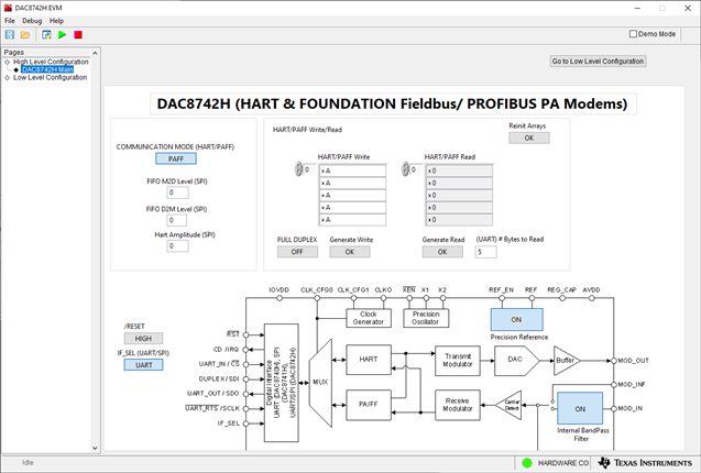
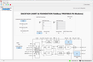
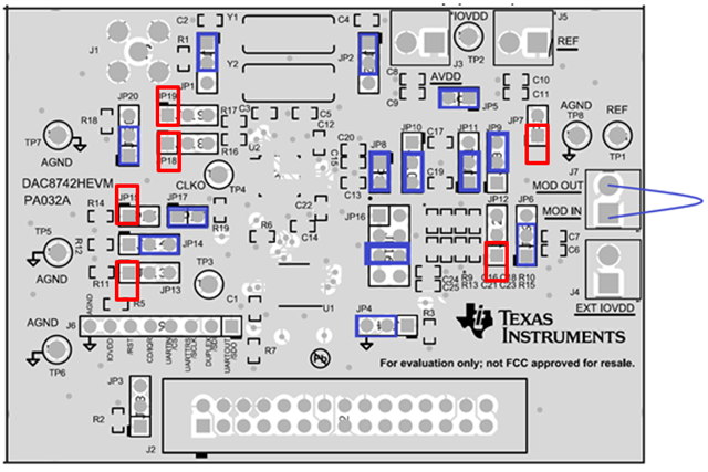
I made the pin configuration like this:

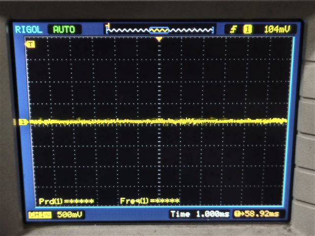
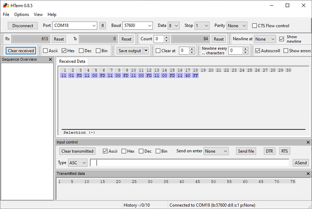
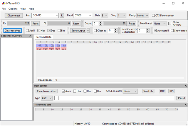
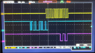
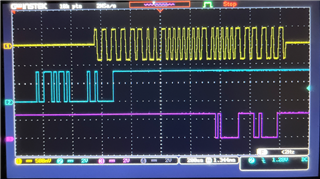
But when I try using UART mode, I didn't receive any data.

Could you help me about this issue?

Thank you for your help.

Regards,

Ibrahim

  • Ibrahim,

    Can you please set the JP13 shunt to connect pins 2 to 3? I think this will set the device to communicate in UART mode.


    Joseph Wu 

  • Dear Joseph Wu,

    I connect pin2 to 3 on JP13, but still didn't get any data. Did I make some mistake?

    Thank you,

    Regards,

    Ibrahim

  • Hi Ibrahim,

    UART reading requires the amount of bytes to be filled in for the GUI. (I saw your first example you read 5, but your most recent picture had 0)


    Thanks,
    Lucas

  • Hello Lucas,

    Thank you for your advice, now I can receive the data in UART mode for HART communication. 

    But, for PAFF communication in UART mode I can't receive the data.

    Could you help me about this? Thank you.

    Regards,

    Ibrahim

  • Hi Ibrahim,

    Can you measure the signal on the MOD_IN/MOD_OUT pin?
    It would also be useful to compare it to the PAFF generated by SPI.

    Seeing the UART message being sent to the DAC8742H would also be useful.

    Thanks,
    Lucas

  • Dear Lucas,

    Here is the signal on MOD_IN/MOD_OUT for HART Communication in UART mode.

    I can't get the signal on MOD_IN/MOD_OUT for PAFF Communication in UART mode.


    Here is the signal on MOD_IN/MOD_OUT for PAFF Communication in SPI mode.

    I can receive the UART data for HART Communication, but I didn't receive anything for PAFF Communication. I use 1200bps, 8 Data, 1 Parity Odd.

    And could you tell me, what is serial configuration for PAFF Communication?

    Thank you,

    Regards

    Ibrahim

  • Hi Ibrahim,

    The GUI was sending the 1200 BAUD UART, correct? If so, it appears that the GUI is not formatted correctly for PAFF UART communication.

    The expected UART is 57600 BAUD with 4 bytes at the beginning of the message to configure the PAFF message. (Page 17 of the datasheet, Section 7.4.2).
    The UART has 1 start bit, 8 data bits, no parity bit, and 1 stop bit, which is 8N1 format.

    If you have the equipment for an external UART controller, I would use that. I'll look into updating the GUI to address this issue.

    Thanks,
    Lucas

  • Dear Lucas,

    I set this configuration on GUI:

    Here is the data that I receive for PAFF Communication in SPI Mode:

    But for PAFF Communication in UART Mode, I still didn't get any data. I use 57600bps, 8N1 seial configuration.

    Could you give me some advice? 

    Thank you for your help.

    Regards,

    Ibrahim

  • Hi Ibrahim,

    In your second picture, is that what the GUI is sending to the DAC on UART?

    If not, can you provide a picture of your UART write to PAFF?

    Thanks,
    Lucas

  • Dear Lucas,

    In the first picture I send data with the value "AAAAA" via PAFF Protocol and SPI Mode.

    In the second picture I captured the data sent by the first image (AAAAA) through UARTOUT Pin.

    Thank you,

    Regards, 

    Ibrahim

  • Ibrahim,

    Similar to you, I was able to get the PAFF running through SPI. However, I was not able to get PAFF running through UART. For now, I'm still looking through it. I do see a UART signal on UARTIN, so the UART is making its way to the device. However, I don't see anything MODOUT.

    I'll keep playing with it, but I'm not sure what I'm missing in the setup. Are you able to set the UARTIN going to the device? I just want to make sure that you have that signal going in as well.

    Joseph Wu

  • Dear Joseph,

    I try to send some data (AAAAA) via PAFF Protocol and in SPI Mode:

    And I try to capture the data through UARTIN Pin and I able to get the UART data:

    But in DAC8742H EVM GUI I didn't get any data:

    Could you give me some advice?

    Thank you,

    Regards,

    Ibrahim

  • Hi Ibrahim,

    For UART PAFF communication, there needs to be 4 bytes at the beginning of the UART transmit to configure the PAFF settings.

    I don't think it will send if these aren't provided.


    Can you try sending EA 99 00 AE as your first 4 bytes and then include any data bytes after it in the same write?
    Ex: EA 99 00 AE 12 34 56 78 90 ?

    Thanks,
    Lucas

  • Ibrahim,


    I haven't completely gotten it to work, but I am closer to it.

    I set up the board just so that I could see the PAFF signal, but haven't run it back yet to the MOD_IN to check the receive of the PAFF signal. Here I just send the MOD_OUT to a wire just to view that the PAFF comes out.

    Here are the jumper settings for the board. The main things that I needed to check were the setting for JP15, so that the signal going into CLK_CFG0 is midway between IOVDD. This is achieved setting JP15 and JP17 shunt the jumpers. After that, I want to use the 4MHz crystal, so I set JP1 and JP2 to the 2 to 3 shunt. Also, I want to use UART as the interface, so I set IF_SEL to ground shunting 2 to 3 on JP13. You can see the settings, on the diagram on the board.

    I need to check the settings for JP6, JP10, JP11, and JP16, I should be able to get a signal to MOD_OUT.

    After that, I set the configuration on the GUI. I set IF_SEL to UART, set COMMUNICATION MODE to PAFF, Enable the internal reference, and then set MOD_IN to internal bandpass filter. Then, I set the HART/PAFF write to 0xEA, 0x90, 0x00, 0xAE, 0x01, 0x02. I think Lucas's suggestion of the first four specific bytes are required for transmission.

    At this point, I can look at the UARTIN signal sending the data to the device, and then I can see the MOD_OUT sending the PAFF signal. Here's what it looks like with an oscilloscope.

    The blue trace is the UART signal, the yellow trace is MOD_OUT, and the pink signal is just the internal reference. Again, I haven't tried to loop the PAFF signal to MOD_IN yet, but that's the next step. I just wanted to make sure that I can see the PAFF signal on MOD_OUT.


    Joseph Wu

  • Ibrahim,

    Just in case you need this, here's how my GUI is set up:

    Joseph Wu

  • Ibrahim,


    I think the EVM works with the setup I described in the previous post. I connected the MOD_OUT to MOD_IN and ran the device in the same way. With this connection, in full duplex I re-connected the scope and looked at the MOD_OUT, UARTIN, and UARTOUT lines. Yellow is MOD_OUT, blue is UARTIN, and pink is UARTOUT. Again, I sent a sequence of 0xEA 0x90 0x00 0xAE 0x01 0x02. This is what it looks like after I send the same sequence:

    Here it is again, with a close up of the transmission side, particularly for UARTOUT:

    For the read, I did set the stack to read 2 bytes and I was able to generate the read and get the last two bytes:

    This looks like it works. You can see the UARTOUT from the scope, and you get the same thing from the GUI.


    Joseph Wu

  • Dear Lucas,

    Thank you for your advice, sorry for late reply, I was on annual leave.

    Could you share that document? I didn't have the document.

    Thank you for your help.

  • Dear Joseph,

    Sorry for late respon, I was on annual leave. Thank you for your help.

    I followed your pin configuration and now I able to send data via PAFF protocol through UART.

    Do you have some document about the data format for PAFF protocol communication?

    Thank you,

    Regards,

    Ibrahim

  • Ibrahim,


    The setup for the transmission of the PAFF data is done through a four byte sequence as described in section 7.4.2 in the datasheet that describes the UART interfaced PAFF communication. The four bytes are shown in a diagram of the bytes and their fields on pages 17 and 18 of the datasheet.

    As for documentation for the specifics of the PAFF protocol communication, we don't have any documents to provide. We've done much more with the HART protocol, and there is some documentation for that.


    Joseph Wu