This thread has been locked.

If you have a related question, please click the "Ask a related question" button in the top right corner. The newly created question will be automatically linked to this question.

DAC8760: Questions regarding schematic

Part Number: DAC8760
Other Parts Discussed in Thread: OPA192, , , TIPD119

Hi, I have some questions, could you please help me?
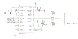
1. Unused HART-IN
Do I have to tie HART-IN pin to GND through a 22 nF capacitor or can I leave it floating?

2. Does the DAC only support SPI mode 0?

3. LATCH
Can I tie this pin (/CS) to GND?

4. CMP capacitor
Do you recommend to add a capacitor (e.g. 1 nF) connected between VOUT and CMP pin?

5. DVDD and DVDD-EN
I use a 3.3 V microcontroller. Is it ok to interface the microcontroller with the DAC without connecting an external 3.3 V power-supply but using (for DVDD) its internal 5 V supply then leave DVDD and DVDD-EN pins unconnected?

6. ISET-R
Do you recommend to connect a 15 kOhm resistor to ISET-R?

7. Single-supply operation
I am interested in 0 (or 4)-20 mA and 0-10V output, is the DAC in single supply mode ok? E.g. AVDD = 24V and AVSS = GND
Do you recommend to regulate the voltage or can I directly use the voltage from a 24V wall adapter?

8. What do you recommend for power saving when the analog output is not necessary?

9. IOUT and VOUT
I short the pins IOUT and VOUT. Do you recommend adding resistors, e.g., 15 Ohm and/or capacitor e.g. 100nF?

10. VSENSE
Is it highly recommended sensing the load using VSENSE?
Can I simply connect +VSENSE to VOUT with another 15 Ohm resistor and tie -VSENSE to GND?
In other application notes an OPA192 is used, do you recommend that I use it as well? In case, could I use it in single supply (24V) mode see above?

11. CAP1 and CAP2
I want to leave CAP1 and CAP2 unconnected, do you see any downsides?

12. Currently, I don't have galvanic isolation, I don't have space for an isolator. Is that a problem?

13.  What minimum EMC protection should I provide?

14. Do you have any other recommendations?

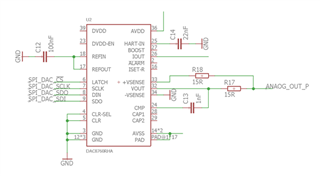
Thank you for your support!

  • Matteo,

    Here are a few answers for you about the DAC8760:

    1. I would tie the HART-IN to GND through the 22nF capacitor to ground.

    2. The DAC only supports SPI mode 0.

    3. Yes, the LATCH can be tied to /CS. Data is latched in at the rising edge of /CS.

    4. The CMP capacitor is used to give a little more stability to the output with capacitive load. There is some guidance on the capacitance in the datasheet in the pin list on 4. Generally I would not use a capacitance greater than 470pF from CMP to VOUT.

    5. The DVDD internal regulator in the DAC8760 has an output of 4.6V. Some microcontrollers have digital inputs that are tolerant to higher voltages, but in this may not be the case for your system. If your micro is using 3.3V, then I'd probably disable the internal regulator and bring over the 3.3V from your micro.

    6. I would use the internal 15kΩ resistor. This internal resistor is factory trimmed and has a better tolerance and drift than an external resistor unless you're able to get a better than 0.1% resistor.

    7. I would use a regulator to get the voltage to what you want instead of a wall adapter. Wall adapters can be very noisy and poorly regulated.

    8. I'm not sure what you mean by this. Can you clarify this question? When you have the outputs disabled, the device draws about 3mA from AVDD and less than 1mA from DVDD. I think that's the minimum current that will be drawn, short of disconnecting the supply.

    9. I did find an app note on combining IOUT and VOUT. The link is below:
    https://www.ti.com/lit/an/sbaa199/sbaa199.pdf

    There's also a "Combined Voltage/Current Output with Surge Protection Reference Design" that has a bit of a write-up. You can find that here:
    https://www.ti.com/tool/TIDA-00559

    10. The +VSENSE completes the feedback loop for the output amplifier for the voltage output DAC. A 15Ω resistor would add a tiny amount of error, but it would also give a little protection to the device from surge events. I'm not sure which app note references the OPA192, but you can also use that amplifier as part of the feedback to add an extra layer of protection, particularly to over-voltage events.

    11. I don't think there's a downside to leaving CAP1 and CAP2 unconnected. If I think of anything, I'll re-post something.

    12. I've seen plenty of circuits that use and don't use isolation. This is going to be dependent on your application.

    13. One of the evaluation modules that we have for this device is the DAC8760EMC-EVM. You can find it in the link below:
    https://www.ti.com/tool/DAC8760EMC-EVM

    There's a little description on the EVM and you can review the circuit in the EVM user's guide.

    14. If you are using this device, I highly recommend getting the EVM just to play with the part. It does a pretty good job walking through the operation with the GUI through a USB connection.


    Joseph Wu

  • Hi Joseph,

    Thank you for your reply.

    7. Are 12 V for AVDD and GND for AVSS ok?

    8. I mean, if the analog signal is not needed I might want to "turn off" the DAC completely.

    10, 13. OPA192 can be found in TIPD119 but also in sbaa199.pdf (page 12)
    I think about whether a buffer and some diodes are needed. However, do you recommend that I keep the three 15 Ohm resistors?

    Thank you. Best regards,
    Matteo

  • Matteo,


    7. Generally, operating the device with AVDD=12V and AVSS=GND is ok. However, you will have some drive limitations for the DAC itself. If you imagine the output of the DAC is driven by an opamp with 0 to 12V supplies, you're not going to be able to output to exactly 0V or exactly 12V. For the top end, you shouldn't have a problem. The headroom for this output is 0.5V which means the output could theoretically be driven to 11.5V. For the voltage output, the maximum range is 11V, so you wouldn't have any problems with that. For the bottom end, the footroom is 0.5V, which means that any output below 0.5V for a DAC setting may be inaccurate. If you wanted to the full range of the DAC output, you would need some sort of bipolar supply.

    8. If the analog signal is not needed, then the closest you could get to a minimum power would be to disable the output and you'd get that 3mA of current I mentioned. Other than that, you might be able to put in a FET to disconnect the supply, which would cut that current to 0 of course.

    10, 13. I'm not sure if your application absolutely needs protection, but I always recommend it. I think the resistors, opamps, and diodes protect against both ESD and overvoltage events. I would also note that we also recommend a 10Ω series resistance going to AVDD and it's shown in the datasheet.

    If you do put together a circuit, let me know and I can review it when you're ready.


    Joseph Wu

  • Matteo,


    I did review your schematic, but I posted the response back here. It's easier for me to keep track of these questions on the forum instead of through messaging. However, there wasn't too much in your schematics that we hadn't talked about before.

    I don't really have a bidirectional ESD diode to recommend. I'm not too familiar with that product line. Most of what I would recommend comes from the application notes or evaluation modules that we've tested. Additionally, a diode like that is generally going to be larger than an 0805 footprint. For most of those devices, the size is needed to ensure that the device can handle a large event by shunting a large amount of current, if only for a short time period.es significantly depending on load. A resistive load or a load sinking current might be able to get closer to the ground than a no-load or light load output.

    I'm not sure what you would use for the wall adapter. There are devices like the TPS7B6950 which would be a low dropout regulator. This device has a max input of 40V, and will regulate the output to 5.0V. I don't know of who you'd ask, but you can post back to E2E asking about the device. You can find a link to the device here:

    https://www.ti.com/product/TPS7B69

    You can use the message app, but I'll post responses back here, unless we need to discuss real specifics on your board that might be sensitive.


    Joseph Wu

  • Hi Joseph,

    Can you explain why the 10 ohms to AVDD is important? In the two EVAL-Board this resistor is missing.

    Do you recommend that I leave both 15 ohm resistors or since VOUT/IOUT are combined keep only one?

    Thank you fpr your support
    Matteo

  • Matteo,


    The 10Ω resistors were added to the datasheet after noting that fast supply transients might cause an in-rush current that could damage the device. This is referenced in the caution note that we put in the Power Supply Recommendations section in the datasheet on page 52. Even if you don't have a fast supply ramp, there might be ESD events that could cause fast transients. For that reason, we started recommending a modest resistor in series with AVDD.

    For the resistors, they also help with protection of the device. I would still add both of them to protect each output.


    Joseph Wu

  • Hi Joseph,

    To optimize the BOM how would it be if I chose for the AVDD resistor also 15 Ohm?
    Or if I change to 10 Ohms those for IOUT and VOUT?

    Thank you,
    Matteo

  • Matteo,

    I think it would be better to keep the IOUT/VOUT resistors at 15Ω. For the AVDD series resistor, going from 10Ω to 15Ω, I don't think it would make much difference except to take up a bit of headroom voltage. However, the extra 5Ω on 20mA would only be 0.1V in headroom.

    Joseph Wu