This thread has been locked.

If you have a related question, please click the "Ask a related question" button in the top right corner. The newly created question will be automatically linked to this question.

ADS1278EVM-PDK: Designing an IEPE excitation source for the ADS1278V2EVM evaluation version

Part Number: ADS1278EVM-PDK
Other Parts Discussed in Thread: ADS1278, ADS127L11, TIDA-010249, OPA4187, OPA2320, TLV61046

Tool/software:

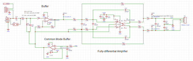
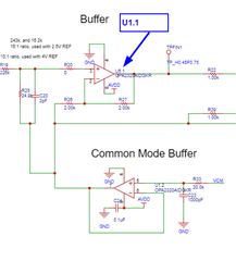
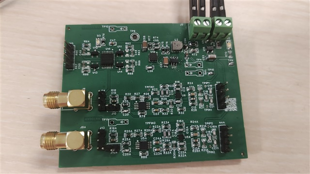
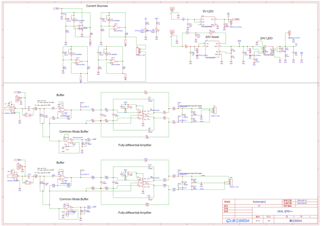
I noticed that the ADS1278 can be applied to sound signal and vibration signal acquisition, but I didn't notice that the ADS1278V2EVM doesn't have an IEPE excitation source for its analog input interface. So I had to design my own IEPE excitation source short circuit.


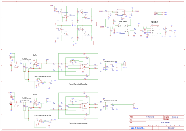
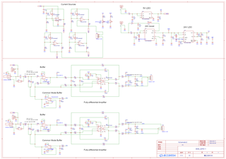
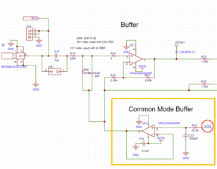
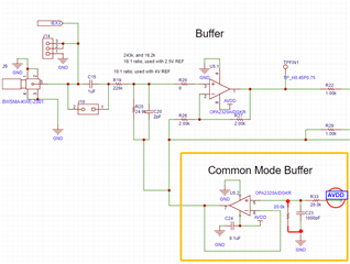
I've learned about the ADS127L11 design 4-channel IEPE signal acquisition program before, can you provide a design (or a PCB schematic)?


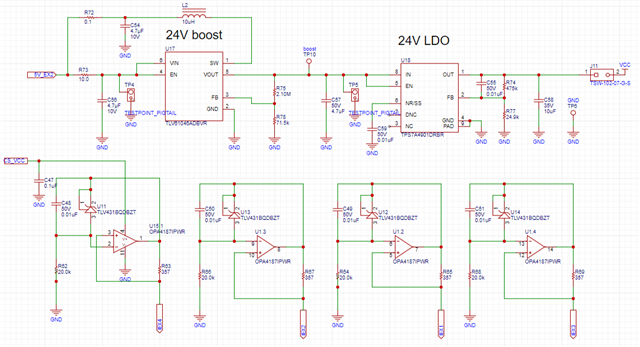
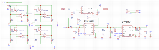
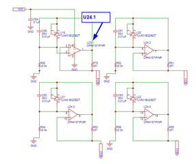
Can I apply the IEPE excitation circuit part of the ADS127L11 scheme to my ADS1278V2EVM part? As shown below, is it possible to input lex1-4 to my AINP1 connector and connect this connector to my sensor?

Any help you can provide would be greatly appreciated!

ADS127L11_iepe

  • Hello,

    If you want to interface an IEPE sensor to the ADS1278, then you will need the full input signal chain used in the IEPE sensor design, including the fully differential amplifier to drive the ADC inputs.  If using the ADS1278V2EVM, then channels 1-4 already include this amplifier, so you would not need to duplicate this if using the EVM for initial system evaluation.

    The full design files for the IEPE reference (TIDA-010249) are available at the below link:

    https://www.ti.com/tool/TIDA-010249

    Regards,
    Keith Nicholas
    Precision ADC Applications

  • Thank you very much! Can you provide more information? I know relatively little about this and if you could provide me with more help it would save me a lot of time!

  • Hello,

    I'm not sure what questions you have?  All of the design files are available in the TIDA-010249 folder.  The below signal chain is complete; if you copy this and connect directly to the AINPx and AINNx pins of the ADS1278, you will get good performance, similar to the reference design.

    Regards,
    Keith

  • OH i see,thank you very much!

  • Hi keith, thank you very much for your help! I have designed the circuit again, I have designed the IEPE excitation source circuit and the fully differential amplifier circuit; the circuit diagram is below:

    For channels 1-4 I simply connected the LEX line of the IEPE excitation source to AINP of the ADS1278EVM; the signal to be measured is input from AINP_SMA of the ADS1278EVM;

    For channels 5-8 I connected the IEPE excitation source circuit and the full differential amplification circuit together, and connected the outputs AINP, GND, GND, and AINN to these pins of the ADS1278, and the inputs to be measured were input through J9;

    Here's my overall schematic, and I'm going to hit two identical PCBs for the 8 channels;

    Since I know very little about this before, I would like to ask you to confirm this before I hit the PCB, and I would be very grateful if you could check this for me!

  • Hello,

    This looks correct.  Make sure all of the VCC nodes, AVDD nodes are correctly connected to the same NET on your board design.

    Also, The OPA4187 is a quad device (4 independent amplifiers).  Each of the 4 channels should use the same OPA4187, all should be part of U24.


    Same suggestion for the Buffer and Common Mode amplifiers; both of these amplifiers should be part of the same dual OPA2320.

    Also, the TIDA-010249 was design to use a single 5.5V power supply, which is why the TLV61046 boost converter is used to convert 5.5V to 25V.  You only need this boost supply if you intend to use a single 5.5V power source.  If you have an external 24V source available, then you can omit this circuit.

    Otherwise, everything looks correct.

    Regards,
    Keith

  • Hi, Keith. Thank you very much for double checking, this is indeed a very serious error.

    (I have a 5V power supply, but I don't have a 24V power supply; moreover, since I don't know enough about this part, I try not to change the circuit too much to avoid bringing more uncertainties)

    I have corrected both errors and when I did another check I found a new problem:
    In the TI-010249 program, the VCM pin here should be connected to ADS12L11, but the circuit I designed does not have this pin;

    I checked some information:
    The datasheet for the ADS127L11 shows that: the VCM pin provides a buffered output voltage at the midpoint of the AVDD1 - AVSS supply; AVDD1 = 5V and AVSS = DGND, so the input to the VCM should be 2.5V; it also says that the VCM can be left off;

    So I'm asking: can I remove this part of the circuit? If not how do I design this part of the circuit?

    Thank you very much!
    I wish you all the best!

  • Hello,

    You just need a mid-supply voltage for VCM.  In this system, since you are using a unipolar 5V supply (AVDD=5V), you can simply add another 20.0k resistor to GND, and connect the VCM to AVDD.  This will generate a common mode voltage on the output of the buffer of 2.5V.

    Regards,
    Keith

  • Thank you very much! I learned a lot!
    Have a nice day!

  • You are welcome.

  • Hi, keith! Thank you very much for the help you gave me before, unfortunately now I have a new problem.

    As you can see in the picture below, I did a PCB punchdown of the schematic we discussed.
    It ended up looking like this:

    But when I connected 5V power to it, white smoke was generated at pin U17 and I immediately disconnected the power.

    I have investigated this situation, and found a mistake: U17 is sot23-6 package, I did not understand it clearly, so it led to the patch paste the opposite; well, I found the phenomenon is not normal after I power on and power off, but I'm not sure whether it will have an impact on other components?

    Now I have re-pasted the new U17, but it is still not right: when I give it J1 and J3 at the same time connected to the 5.2V power supply, its two lamps do not light up, and sometimes there is even a "hissing" sound, using a multimeter to measure the TP10 it does not output a voltage of about 24V.

    I have now patched two boards and they have the same phenomenon. I have double checked the soldering and there is no soldering.

    Could I possibly have a power supply problem? I've used two power supplies to try: one is an adjustable DC regulated power supply (the vendor says it's in constant voltage mode and automatically adjusts the current according to the load; I've used it to power my ADS1278 evaluation board just fine at 6V500ma), and the other one is a 5V power supply (a multimeter goes directly to the current and measures it at about 5Ma); they're both the same phenomenon.

    Where is the error that caused this situation? Can you give me some help?

    Sincerely
    Have a nice day

    Altium_0608_IEPE++_2024-06-20.zip

  • Hello,

    I am out of office and will reply on Friday, June 21. 

    Regards,

    Keith

  • Hi, keith! 

    I found a few things by troubleshooting myself:

    1. The reason the two diodes don't light up is that I put them on backwards

    2. TP11 is normal 5.01V; but TP5 is about 16V, not normal 24V;

    3. There will be a hissing sound, I check the information seems to be the L2 power inductor whistling

    4. U17 will have white smoke

    So the problem should be in L2 and U17, I have placed an order for a new device, can you help me to see if there is any design unreasonable place?

    Sincerely
    Have a nice day

  • Hello,

    The TLV61046 has a maximum input voltage rating of 5.5V.  If you exceed this voltage, then this would explain why the part is damaged.

    Also, you need to make sure the inductor current rating is correct, else the inductor can saturate resulting in the the boost circuit not working correctly.  The reference design uses the following inductor rated for 2A:

    FDSD0420-H-100M
    MuRata Toko
    Inductor, Shielded, Powdered Iron, 10 uH, 2 A, 0.2 ohm, SMD

    For further questions on the boost converter, you should post another e2e questions specifically for this device.

    Regards,
    Keith