ADS1298ECGFE-PDK: AC lead off detection for skin-electrode impedance measurement during ecg acquistion.

Part Number: ADS1298ECGFE-PDK
Other Parts Discussed in Thread: ADS1298

Tool/software:

Hi,

Can I know how may i do this in a step by step procedure since the led's displaying the connections with respect to the electrodes are fluctuating a lot irrespective of the lead being connected or not. 

And how are the individual channels linked with respective to the leads to tell which lead is off or not via the EVM software.

I have enabled the ac lead off detection feature, lead-off current and all the registers that is the LOFFP,LOFFN,LOFF FLIP and the RLD SENSE bits. 

Is it mandatory to enable the WCT and Augmented lead channels too? 

How can i calculate the impedance after ecg data acquisition to set a minimum threshold to know if the electrode connectivity is good?

  • Hello Samiksha,

    Thank you for your post.

    The LED indicators on the EVM GUI are for DC lead-off detection only. These LEDs reflect the status of the comparator outputs, which are reported in the LOFF_STAT[4:0] bits of the STATUS word. They cannot be used in conjunction with AC lead-off detection.

    It is not mandatory to enable WCT or augmented lead calculations in the ADS1298 if they are not used.

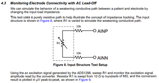
    Impedance calculations must be done in post processing based on the amplitude of the signal acquired at the lead-off frequency.

    Regards,

    Ryan

  • Hi Ryan,

    Thank you for the response. 

    May i know for the impedance calculations part, how exactly do I set the lead-off frequency for the AC signal and acquire its amplitude to know if the particular electrode connectivity is good or bad? 

  • Hello Samiksha,

    Please refer to pages 39-40 of the ADS1298 data sheet for more details about how the AC and DC lead-off detection is implemented. The determination of connectivity status is completely up to the user to determine based on their own trials and analyses.

    We have a some application notes and articles on the ADS1298 product folder which may also be helpful:

    https://www.ti.com/product/ADS1298#tech-docs

    You may find other helpful suggestions on our BIOFAQ page below.

    Link to BIOFAQ homepage

    Regards,

    Ryan

  • Hi Ryan,

    Thank you for response.

    Could you please tell me how the above is performed on the ADS1298 board for AC lead off detection? I'm a bit confused with it.

  • Hi Samiksha,

    What specific questions do you have? The AC lead-off feature and its register settings are described in detail in the data sheet. You may connect an external leaded resistor to any input channel on the ADS1298 EVM.

    Once the data is acquired, you can analyze the magnitude of the waveform in either the time or frequency domain and convert to impedance.

    Regards,

    Ryan