Tool/software:
hi !
Brief description of the problem:
We shorted the input terminals of the ADS1278 evaluation board to GND, communicated with the Raspberry Pi via SPI, and measured data from the Raspberry Pi. The results showed that only channel 1 output was normal, and there were a lot of abnormal signals in channels 2 to 8.
In addition, its sampling rate is not fast enough, only 1.4ksps.
I don't know where the problem is, can you give me some advice?
Problem Description:
### (1) Previous situation:
- Input sine signal, the waveform of channels 1 to 8 read by Raspberry Pi:
(the horizontal axis is the sampling point, the vertical axis is the amplitude)
- The input is short-circuited with GND, and the waveforms of channels 1 to 8 read by the Raspberry Pi are as follows:
### (2) Current situation:
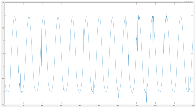
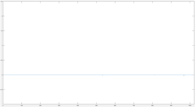
- Input and GND are short-circuited, and the waveform of channel 1 read by the Raspberry Pi is:
(The sampling point of the left picture is 1000, and the sampling point of the right picture is 20000)
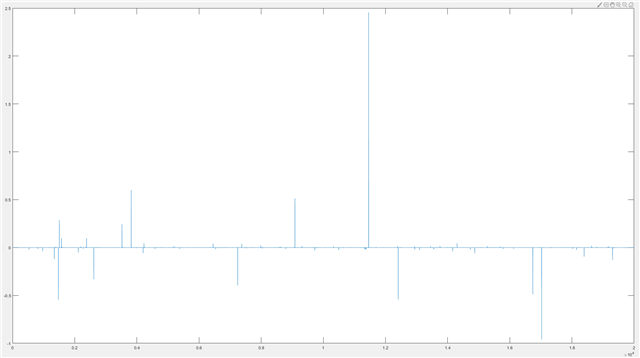
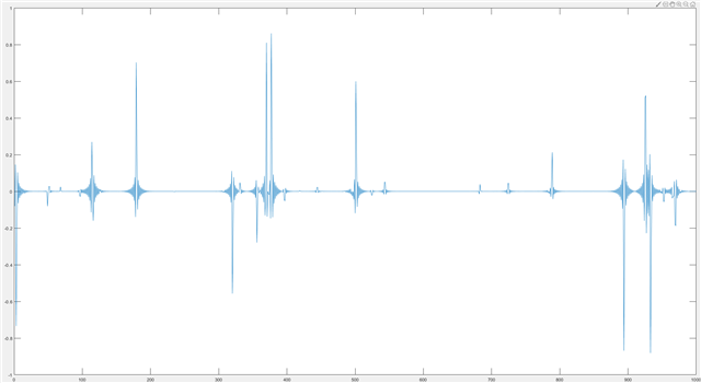
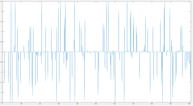
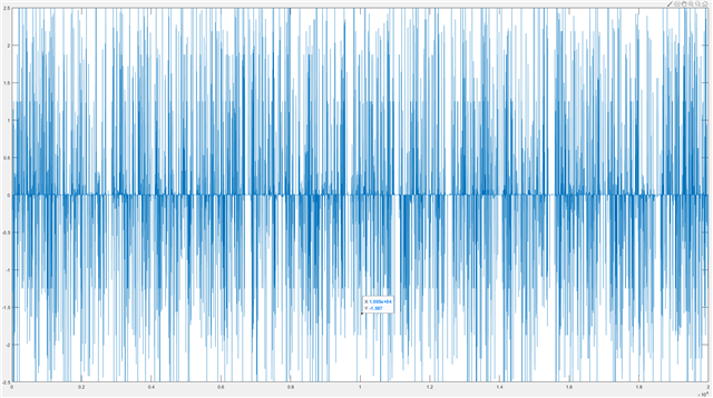
The input is short-circuited with GND. The waveforms of channels 2 to 8 read by the Raspberry Pi are as follows: **There are a lot of abnormal signals**;(The sampling point of the left picture is 1000, and the sampling point of the right picture is 20000)
### 3) The process of the problem in my memory:
- When channels 1~6 are connected to [microphone, constant current source module, differential amplifier circuit], and channels 7 and 8 are still short-circuited, the output results of channels 7 and 8 are abnormal and not 0;
At this time, channels 1~6 may be directly connected to a constant current source signal (4ma);
At this time, channels 1~6 may be mistakenly connected to a high voltage signal; specifically, the microphone may output a 9V DC signal after being excited by the constant current source, and then differentially amplified (uncertain amplification factor) to channels 1~6.

In the ADS1278 evaluation board, the input ends of channels 1 to 4 go through the following circuit (driver input circuit) and then to the ADC chip;
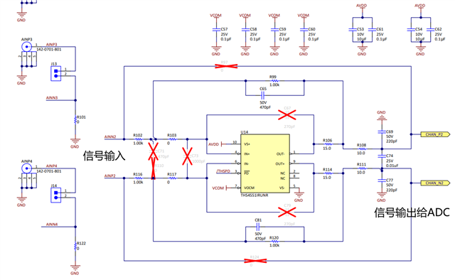
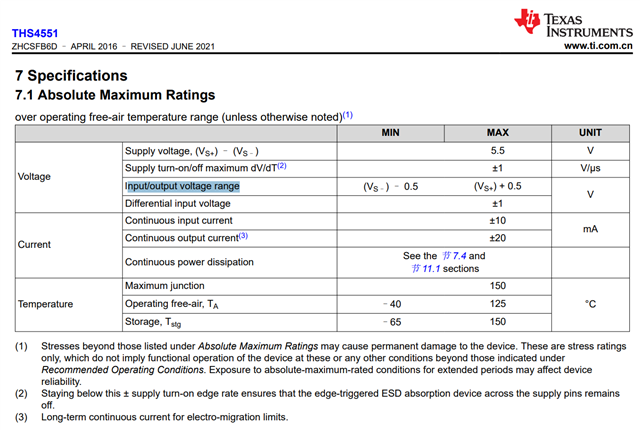
The operating voltage range of THS54551IRUNR is as follows, so it is possible that the input voltage is too large, causing the device to be damaged. But why are the 7~8 channel inputs also broken without receiving high voltage signals?
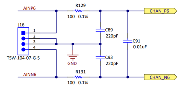
- In the ADS1278 evaluation board, the input ends of channels 5 to 8 go through the following circuit (non-driven input circuit) and then reach the ADC chip;
- Remove the constant current source module and the differential amplifier circuit module, and short-circuit the inputs of channels 1 to 8. As a result, only the output of channel 1 is normal, and channels 2 to 8 are abnormal, as described above.
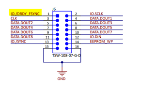
### (4) Wiring and code:
**The wiring has not changed, the code has not changed**; the code can always run normally and realize data collection;
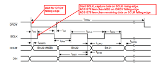
**The data collection mode** is: TDM mode, fixed position data output (regardless of whether a channel is powered off, the channel data remains fixed and is output in the order of channels 1-8);
### (5) Problem speculation
1. Ground supply problem, caused by poor grounding;
2. Impure power supply;
3. Check whether the jumper caps of channels 2 to 8 are conductive (the problem is unlikely)
### (6) Test plan
1. Check grounding
2. Check power supply and other on-board voltages(AVDD\IOVDD\DVDD\VREF)
3. Check wiring and code
4. Use an oscilloscope to check step by step
If you could help I would really appreciate it!
have a nice day !