This thread has been locked.

If you have a related question, please click the "Ask a related question" button in the top right corner. The newly created question will be automatically linked to this question.

ADC12020: Example Circuit design problem in ADC12020 DataSheet

Part Number: ADC12020
Other Parts Discussed in Thread: LMH6550

Tool/software:

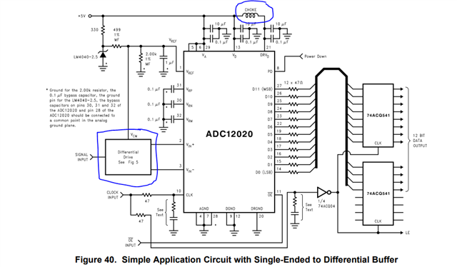
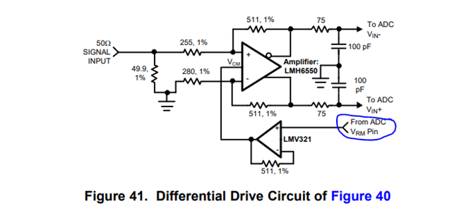
In the ADC12020 DataSheet, figure 40 shows an example circuit of the chip, in which a differential driver circuit is used. The driver circuit uses LMH6550 with a Vcm end, which is connected to the Vcm end of the ADC in figure 40, but in figure 41, the Vrm node is connected to the Vrm node, and the Vrm node of LMH6550 is not connected to the Vrm node of the ADC as shown in figure 40, please show the correct connection method. What's more , CHOKE inductance is used in figure 40. What are the recommended parameters?

Thank you for taking your time to deal with this case and look forward to your reply.

  • Hi,

    On page 19 of the datasheet under the "Input Common Mode Voltage" section it says you can use either the VCM or the VRM pin to supply the common mode voltage to the LMH amplifier.

    For the choke/ferrite bead, please use the following:

    Ferrite Bead, 120 ohm @ 100 MHz, 0.5 A, 0402 402 74279271 Wurth Elektronik

    This will work fine.

    Regards,

    Rob