This thread has been locked.

If you have a related question, please click the "Ask a related question" button in the top right corner. The newly created question will be automatically linked to this question.

DAC8775: BUCK-BOOST converter implementation

Part Number: DAC8775

Tool/software:

Hi,

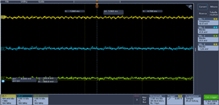
I'm trying to program the DAC8775. I followed the setup guide exactly like Brian did, but I ended up with an output of 0V, with a lot of noise. 

Status Register returns meaningful values and when I write in register 0x02 on bit UBT, I receive a response on bit UTGL of the Status Register.

But when I set Buck-Boost Converter as +-15V, bit PGA, PGB and PGC (I'm using only the first 3 DAC channels) are 0. Instead, if I set PNSEL bits as 10 (positive arm disabled, negative arm enabled) Status Register's bits are 1.

On Status Register, bits FC, FB and FA are never 1, so it makes me think that the DAC output is ok. But, as I told before, it is not.

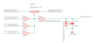
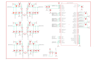
Here is the schematic of Buck-Boost Converters:

I really hope you can help me.

  • Hi Matteo, 

    Thanks for sharing your schematic and procedure. Joseph will review and provide some suggestions soon. 

    Best,

    Katlynne Jones

  • Here are some extra infos.

    Step by step SPI write:

    • RESET SW: 0x01, 0x0001
    • INTERNAL REFERENCE: 0x02, 0x0014
    • SELECT BUCK-BOOST CONVERTER A: 0x06, 0x0001
    • SET BUCK-BOOST CONVERTER: 0x07, 0x61F
    • SELECT DAC A: 0x03, 0x0030
    • OUTPUT ENABLE + OUTPUT +-10V: 0x04, 0xD003
    • SEND DAC DATA: 0x05, 0xC000

    Output schematic:

  • Matteo,


    I would start measuring nodes around your board to make sure the device is coming up the way you expect. When you enable the reference, can you measure the 5V?

    I would start by enabling the positive and negative supplies and measuring them. What voltages do you see before and after enabling them? After that, I would set the DAC range, and then enabling the DAC. If you're in voltage output mode, you would likely see the VPOS_IN_x and VNEG_IN_x voltage set automatically to ±15V.

    If you are able, I do recommend getting a DAC8775EVM and using that to check settings of the device. Regardless, you can use a multimeter and check the voltages as you bring up the board. Let me know what values you see.


    Joseph Wu

  • Hi Joseph,

    I tried to do what you told me. 

    After enabling the internal reference I can measure 5V.

    I measured VPOS_IN_x and VNEG_IN_x before setting it using register oxo6 and 0x07 and it was something like 150mV. Then I enabled BBc on every DAC channel and set it to ±15V, I can measure -15V on the negative arm but I can't measure +15V on the positive one, just as Status Register refers.

    I would try again without the DAC8775EVM, but if I won't be able to make it work, I'll buy it.

  • Matteo,

    Here's what I see using the EVM:

    Powering up the board:

      VPOS_IN_x = 3.3V

      VNEG_IN_x = 0.15V

    Enabling the buck-boost:

      VPOS_IN_x = ~4V

      VNEG_IN_x = ~-6V

    Enabling the DAC in voltage mode in this condition

      VPOS_IN_x = ~+15V

      VNEG_IN_x = ~-15V

    Disabling the DAC in voltage mode and then setting the DAC in current mode and re-enabling DAC:

      VPOS_IN_x = ~4V

      VNEG_IN_x = ~-6V

    To me, it looks like something is clamping the VPOS_IN_x close to ground. I haven't completely looked over your schematic, but you should compare the buck-boost section to the same schematic in the DAC8775EVM user's guide. Do you have a diode reversed someplace to accidentally clamp the VPOS_IN_x to ground?

    Joseph Wu