DAC8740H: Input AND Output HART circuit question

Part Number: DAC8740H
Other Parts Discussed in Thread: TIDA-060020

Tool/software:

TIDA-060020 is the reference circuit for the input scenario while TIDA-01504 is the same for the output configuration.  I was tasked to potentially implement both for greatly customer flexibility.  With that said, would it be recommended to use two separate DAC8740H's to accomplish this?  Is it possible and/or recommended that we use a single DAC8740H as long as both the input and output circuits are not being used simultaneously?

  • Steven,


    In these systems, you would use just one of the DAC8740H for communication. There are carrier detect and request to send signals built into the DAC8740H to avoid data collisions. Additionally, HART is a command/response protocol, so the controller sends a command, and the transmitter sends a response. This also helps keep communication ordered.

    There's information in the DAC8740H data sheet on how to implement HART, but there's a little more information in the following link for A Basic Guide to the HART Protocol.

    https://www.ti.com/lit/an/slaaeh0/slaaeh0.pdf

    Joseph Wu

  • A few clarifying questions.

    • Does either circuit configuration provided above (Analog Input or Analog Output) have anything to do with the Master/Slave digital communication scheme?
    • My application is that of a slave/actuator device.  I am provided a 4-20mA input (Target) from the master/PLC and I provide a 4-20mA output (Position) to the master/PLC.  Which 4-20mA connection would you recommend I use with the HART modem?  Does it matter?

    Thank you

  • Steven,


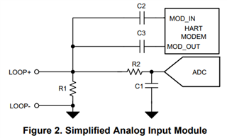
    It seems like you're describing something similar to an analog input module (TIDA-060020). In that design, the input module measures a current, and this measurement sets an actuator. The average current represents the primary variable that is sent from a controller, and a HART signal is superimposed on the current. In the TI design, the input module just shows the ADC to measure the resistive load, but you would add some sort of DAC to control an actuator. I assume the controller only sends a 4-20mA signal into a resistive load.

    In that setup, the input module sends and receives HART signals that are capacitively coupled from resistor to the DAC8740H as shown in Figure 2 of the design write-up. You would have a microcontroller that measure the voltage across the resistor as the primary variable, and then you would used a DAC to set your actuator.


    Joseph Wu