This thread has been locked.

If you have a related question, please click the "Ask a related question" button in the top right corner. The newly created question will be automatically linked to this question.

ADS1220: returns full scale data in Two-wire RTD

Part Number: ADS1220

Tool/software:

Hello,

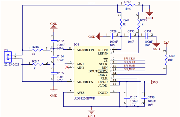
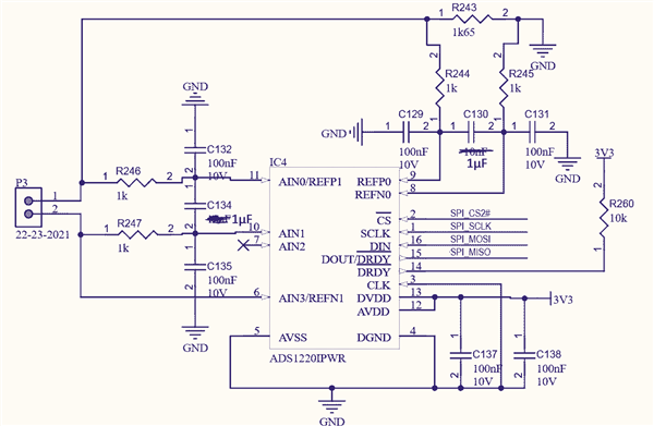
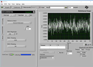
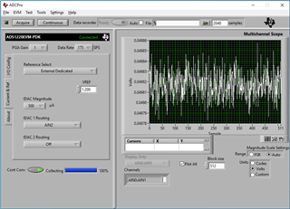
We are having problems with our ads1220 Two-wire RTD connection. We only get the full-scale output from ads1220 with PT100 connected. 

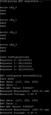
We can send the configurations to our adc and read them via SPI, so we can be sure that the problem is not in SPI. We are using these configurations:

Fullscreen
1
2
3
4
5
6
7
8
9
10
11
12
13
14
15
16
17
18
19
20
21
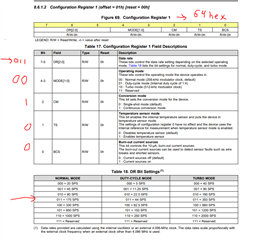
CFG0_PGA_BYPASS_OFF = 0x0
CFG0_GAIN_2 = (0x1 << 1)
CFG0_MUX_P1N0 = (0x6 << 4)
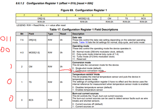
CFG1_BCS_OFF = 0x0
CFG1_TS_OFF = (0x0 << 1)
CFG1_CM_SINGLE_SHOT = (0x0 << 2)
CFG1_MODE_NORMAL = (0x0 << 3)
CFG1_DR_STAGE4 = (0x3 << 5)
CFG2_IDAC_250UA = 0x4
CFG2_PSW_ALWAYS_OPEN = (0x0 << 3)
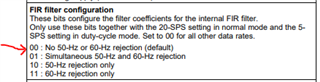
CFG2_FIR_BOTH = (0x1 << 4)
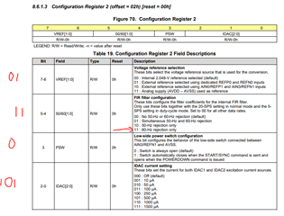
CFG2_VREF_EXT_REFP0_REFN0 = (0x1 << 6)
CFG3_DRDY_DEDICATED = (0x0 << 1)
CFG3_I1MUX_AIN3 = (0x4 << 5)
CFG3_I2MUX_DISABLE = (0x0 << 2)
cfg0 = ADS1220.CFG0_PGA_BYPASS_OFF | ADS1220.CFG0_GAIN_2 | ADS1220.CFG0_MUX_P1N0
XXXXXXXXXXXXXXXXXXXXXXXXXXXXXXXXXXXXXXXXXXXXXXXXXX
 

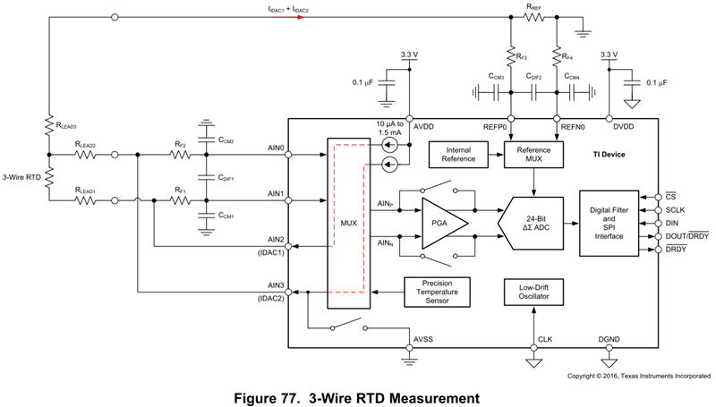
Here is our connections.

  • Hi Samuli,

    The differential capacitor (10nF) in the anti-aliasing filters for the analog inputs is 10 times smaller than the common mode capacitors (100nF). 

    TI recommends that the differential capacitor CDIFF be at least an order of magnitude (10x) LARGER than the common-mode capacitors (CM1 and CM2), because mismatches in the common-mode capacitors can convert common-mode noise into differential noise. This is mentioned in section '9.2.1.2 Detailed Design Procedure' of the data sheet.

    From the schematic, I'm assuming the IDAC excitation current is being configured for the AIN3 pin. Have you tested if there is a voltage drop across the reference resistor to confirm the IDAC current is being set properly?

    From what you have shared, it seems like the IDAC current is being set to '250uA'.

    If this is the case, using a 1.65kΩ reference resistor for a ratiometric measurement, the voltage across the reference resistor will only be ~0.4125V.

    When using an external voltage reference, the minimum Vref voltage should be 0.75V, otherwise you are operating the device outside of the recommended operating conditions:

    Try increasing the value of the IDAC current, or the reference resistor so that the external reference voltage applied is within the values stated in the data sheet.

    It is also always a good idea to probe the SPI communication lines with a logic analyzer to make sure that the digital communication to the device looks okay.

    Best Regards,

    Angel

  • Hey Angel,

    We swapped the capacitors from 10nF to 1μF as you recommended.


    Here is our new connections:


    We also tested the voltage across the 1.65k reference resistor and with CFG2_IDAC_500UA we measured 0.85V. We also measured with different IDAC values to be sure that the IDAC is working. For exampe with 1000uA we measured 1.69V.

    Yet still, with these changes we only receive full-scale values. 


    Here is console prints of our test program output(Configuration registers, Raw ADC data)


  • Hi Samuli,

    Are you issuing a START/SYNC command to start a conversion after setting your register configurations? 

    How are you determining when a conversion result is ready?

    Rather than console prints, can you provide captures of the digital communication of the write/reads to the ADC registers and when doing reads of the ADC data?

    Best Regards,

    Angel

  • adc_troubleshoot.zip

    I've attached a zip with images of the requested captures.
    It contains attempts with both single-shot and continuous mode and the images are numbered in order in which they happened.

    We are issuing START/SYNC when using single-shot mode after setting the registers. This is followed by a 1 second delay, after which we read the 3 bytes.

    In continuous mode we are reading 3 bytes with RDATA command every second after setting the configurations.

    So currently we are only using delays to make sure the conversion result is ready when we read the bytes.

    In every case the 3 bytes read are 7F FF FF.

  • Hi Samuli,

    I'll take a look at these captures and get back to you tomorrow.

    Best Regards,

    Angel

  • Hi Samuli,

    I still need to look at these captures in more detail but should be able to get to them by EOD tomorrow.

    Best Regards,

    Angel

  • Hi Samuli,

    I went through the digital communication captures in detail, thanks for sending these, these are always very helpful when troubleshooting.

    You can write to the configuration registers and read them back correctly which verifies the communication to the device is working.

    One thing to point out, is that you sent two folders, one for continuous-conversion mode, and one for single-shot mode, but in both sets of captures, you are setting the device to continuous conversion mode.

    Both sets of captures you are writing 0x64 (0110 0100b) to configuration register 1, which sets it to continuous conversion mode:

    To set the device to single-shot mode keeping the same settings otherwise, you would write 0x60 to configuration register 1.

    In the continuous conversion mode captures the register settings are the same as the single-shot mode captures, but this time they are correct as you are intending to set the device to continuous conversion mode.

    In the continuous conversion mode captures however, you are not issuing a START/SYNC command after setting the register configurations. This command is needed to start ADC conversions:

    If the command is not used, there is no ADC data to be read when you issue the RDATA command: 

    The IDAC, input MUX, external REFP0-REFN0, and most of the settings are set correctly for your circuit shown in the schematic capture.

    One thing that stood out however, is that in Configuration Register 2, you are enabling 60-Hz rejection:

    This should only be used with the 20-SPS data rate setting in normal mode, but you are setting the data rate to 175SPS in configuration register 1:

    This may be causing the issue.

    Either set the data rate to 20SPS if 60-Hz rejection is desired, or write '00b' to the FIR filter field if a data rate other than 20SPS is desired:

    Also make sure to issue the START/SYNC command before doing ADC data reads after setting your configuration registers, and that you are setting your desired configurations properly (single-shot mode for example).

    It might also be a good idea to monitor DRDY after issuing your START/SYNC to ensure ADC data is ready before doing an RDATA.

    Hope this helps!

    Best Regards,

    Angel

  • Hey Angel,

    We modified the configuration registers as you suggested:

    Register 0: 0x61
    Register 1: 0x60
    Register 2: 0x45
    Register 3: 0x82

    We are not sure if we "need 60-Hz rejection", so we set it off and left the data rate to 175 SPS.

    We also checked the DRDY pin:

    When sending the START/SYNC it goes from low to high for a short time and then back low.
    After that, reading data with RDATA sets the DRDY signal high.

    All we can get is 7F FF FF still.

  • Hi Samuli,

    When sending the START/SYNC it goes from low to high for a short time and then back low.
    After that, reading data with RDATA sets the DRDY signal high.

    Correct this is how DRDY should behave to indicate when new ADC conversion data is ready to be read.

    What you are doing now seems correct so I'm not too sure what the issue may be that you are only getting full-scale readings.

    Have you only tried testing one device?

    The device may have been damaged at some point so it would be a good idea to try a different ADS1220 to see if the results are different.

    You can also try a different configuration with the ADC such as shorted inputs to GND or mid-supply using the internal reference, or a single-ended measurement using the internal reference. To see if you can get ADC output readings that are not full-scale (7F FF FF). 

    These should give something other than full-scale, so if otherwise, the device may be damaged.

    Best Regards,

    Angel

  • Hello Angel,

    I meet the same issue in ADS1220, and i found if disconnect the PT100 while ADS1220 is running, connect the PT100 to ADS1220 again, the result goes well.

    it's very strange, you can check the log below, thanks.

    ADC Code: 8388544
    RTD Resistance Value: 824.993713
    Temp: 9223372036854775807.9223372036854775807


    ADC Code: 8388544
    RTD Resistance Value: 824.993713
    Temp: 9223372036854775807.9223372036854775807


    ADC Code: 8388544
    RTD Resistance Value: 824.993713
    Temp: 9223372036854775807.9223372036854775807


    ADC Code: 1493824
    RTD Resistance Value: 146.914093
    Temp: 122.247627


    ADC Code: 1513664
    RTD Resistance Value: 148.865325
    Temp: 127.435073


    ADC Code: 1515840
    RTD Resistance Value: 149.079315
    Temp: 127.998191

    LEON

  • Hi Leon,

    Thanks for sharing this. 

    It may be worth it to try this and see if it fixes the issue.

    Best Regards,

    Angel

  • I found a similar issue discovered some time ago where with an RTD measurement and the device configured, the first conversion was always wrong. 

    Following a POR, a RESET or POWERDOWN command, the first conversion following START/SYNC was always in error.  In the case of the ADS1220 there is an automatic conversion that takes place following POR and RESET.  The action however differs for the POWERDOWN command that turns off the analog circuitry.  When leaving the POWERDOWN state the START/SYNC command is issued to wakeup the device.

    When the START/SYNC command is issued, the IDACs are turned on which requires time for the IDAC current path to settle for both ADC inputs and reference inputs. 

    Have the following ADC conversion results after the first full-scale ADC reading been checked?

    Best Regards,

    Angel.

  • Hello Angel,

    We followed the command sequence as POR, RESET command, START/SYNC command sent one by one, and the wrong value will continuously output in this condition( tested for 10 minutes at least). when i disconnect PT100, the output value is still 8388544, after i reconnect PT100, the value goes well.

    I also measured the voltage while the wrong value condition, REFP is around 1.65V, and the voltage between VIN0 and VIN1 is the normal value around 55mV.

    Does there have any register or something others that i can check for further analysis.

    Thanks.

    LEON

  • and current register setting is below.

    ADS1220_0_REGISTER: 0x66
    ADS1220_1_REGISTER: 0x04
    ADS1220_2_REGISTER: 0x65
    ADS1220_3_REGISTER: 0x70

  • Hi LEON,

    I can try recreating this sometime early next week on the ADS1220EVM and will get back with my results.

    Best Regards,

    Angel

  • Hello Angel,

    Thank you.

    and the circuit we used is 3-Wire RTD as below.

    LEON

  • Hello Angel,

    I might got the root cause in this issue.

    i found if i config IDAC1 and IDAC2 simultaneously, the error will come out.

    but if i config IDAC2 first, then delay at least 3 seconds(the time might be related to the CAP and RES used as below). and config IDAC1. it works fine.

    R REF = 1.65KΩ, R F3 = R F4 = 1 kΩ, C DIF2 = 100 nF, and C CM3 = C CM4 = 10 nF.

    The log of config ADC register:

    //Config IDAC2

    [09:33:19.141]Temp:10
    ADS1220_3_REGISTER: 0x10

    delay 4 seconds.

    //Config IDAC1

    [09:33:23.544]Temp:70
    ADS1220_3_REGISTER: 0x70

    and if i config IDAC1 first, delay 3 seconds, config IDAC2, it is still wrong in value.

    in the circuit, we can see that we are using external ref, it means that we may need setup external REF first with IDAC2, after the external REF is ready, enable IDAC1 for PT100, then we can do the ADC sample and get the right value.

    Can you help to have a check internally, is it the root cause for this issue?

    thanks.

    LEON

  • Hi LEON,

    Thanks for the update, I will try to recreate this and let you know what I see on my side.

    Best Regards,

    Angel

  • Hi LEON,

    I'll get to this by Thursday.

    Best Regards,

    Angel

  • Hi LEON,

    I now have an ADS1220EVM and a PT-100 3-wire RTD with me.

    I will set my hardware and use the ADS1220 EVM GUI to recreate this setup and share my results with you early next week.

    Best Regards,

    Angel

  • Hi,

    I recreated a 2-wire and 3-wire RTD setup on the ADS1220 EVM.

    I used a 100 Ohm resistor for the 2-wire RTD, and the reference resistor on the EVM was 2.4kOhms.

    Gain = 1, PGA disabled, 175SPS DR.

    The followings are the results for when the IDAC was set to 1mA (VREF = ~2.4V, voltage through resistor measured = ~100mV).

    The following is the results for IDAC set to 500uA (VREF = ~1.2V, voltage through resistor measured = ~50mV).

    For the 3-wire RTD, I used an actual PT-100 3-wire RTD, reference resistor = 2.4kOhms.

    Both IDACs were set to 500uA.

    VREF = (IDAC1 + IDAC2) * 2.4kOhms = (500uA + 500uA) * 2.4kOhms = ~2.4V

    Voltage measurement through RTD element = (IDAC1) * (~100Ohms) = (500uA) * (~100Ohms) = ~50mV

    Results when IDAC1 was turned on first, then IDAC2:

    Results when IDAC2 turned on first, then IDAC1:

    There wasn't any significant difference in the results due to the order of the IDACs being enabled. As long as everything is settled the results should be okay, maybe all that is needed is a small delay between when the device is set up and when you start taking conversions to ensure this.

    There is some noise, but the results are what is expected and the 2-wire and 3-wire RTD setups should work on the ADS1220.

    Best Regards,

    Angel

  • Hello Angel,

    Thanks for the efforts and details. we will do further test on this, may need using oscilloscope to capture the waveform carefully. it might be related the circuit customer designed, your suggestion of "small delay" is the major focus that we will let customer to have a try and test.

    Thank you.

    LEON