This thread has been locked.

If you have a related question, please click the "Ask a related question" button in the top right corner. The newly created question will be automatically linked to this question.

ADS1220: 3-wire RTD sensor open status check problem

Part Number: ADS1220
Other Parts Discussed in Thread: ADS1247

My customer have a requirement to check sensor status(Open or short).

The easy way is use the burn-out current, but this will influence the normal measurement, so customer want to use other way to detect the status.


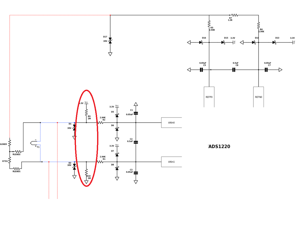
Can we use the pull-up /low resistor as shown below? If yes, how to design the value of the two resistors?

Looking forward to your reply, thank you.


  • Hi Marc,

    Generally you want to use as high a resistance value as possible to limit the amount of current added to the measurement.  Any leakage can create an error as diodes tend to be leaky.  If enough current flows through the filter resistors it is possible to measure a difference voltage.

    I would say 1M ohm is the minimum, but I would try 10 to 20M with a max of 50M ohm.

    The drawing appears to be a low-side reference, but this drawing shows no path to AGND for the IDAC current.  Junction of R6 and R7 should go to AGND.  Also, the connection for the AIN1 and AIN0 also appear to be backwards.  AIN1 should connect to AINP of the ADC and AIN0 should connect to AINN.  Also, R9 should connect to AGND and R10 should connect to VCC for this configuration.  Or, you could reverse the RTD connections appropriately.  Take a look at section 9.2.2 of the ADS1220 datasheet on page 52.  Figure 77 shows a typical RTD connection for 3-wire RTDs.

    Best regards,

    Bob B

  • Hi Bob,

    Thank you for your detailed reply and correction to the design errors.

    I use TINA to simulate the RTD open with external pull-up/down resistors, and the result is as below. (I use ADS1247 to replace ADS1220 just for simulation)

    As you can see, VF1 goes to 10kv and VF2 equals to IDAC2*RREF; It's not a good result and I can't use this to determine whether the RTD is open.

    Customer wants to detect the RTD open status without using BCS because it will interrupt the normal work; do you have any suggestions to solve this problem?

    Thank you so much.

    Best regards,

    Marc

  • Hi Marc,

    The problem is with the simulation.  Generating 10kV from a 3.3V source would be very impressive, but not possible.  In this case the constant current source will not provide current as the IDAC compliance has not been met.  There has to be a current path to AVSS.  In this condition AINP will be pulled high and AINN to 820mV.  The result should be positive full-scale.

    Best regards,

    Bob B

  • Hi Bob,

    Thank you for your reply. I did lab test and it works.

    Merry Christmas and Happy New Year!

    Best regards,

    Marc