


Hi there,
I use the ADS1220 for 4- wire RDT measurement. My board has 24 x ADS1220 populated and I'm using a multiplexer for the SPI SS line to read out the temperatures sequentially. Everything is working well but now I also have to add 8 differential voltage measurements to this project. The voltages range from 8-22 mV.
At this stage, I'm trying to proof concept and have 8 extra blank 4-RTD PCB's from the manufacturer as I only had the choice to order 10 as a minimum quantity from the PCB supplier. If I can utilize these also for the voltage measurements in the meantime that would be great. I would do a proper PCB design later. The project is still at proof of concept stage. Can I just configure the ADS1220 to thermo couple settings and scratch the R3 lead wire track? I believe I still achieve reasonable resolution.
If the ADS1220 is suitable, is there a schematic/ circuit available for 2 differential measurements so I can cover 2 measurements with one ADS1220?
I'm trying to avoid having to use and learn about another chip as I'm already familiar with the ADS1220 and have a few spare chips.
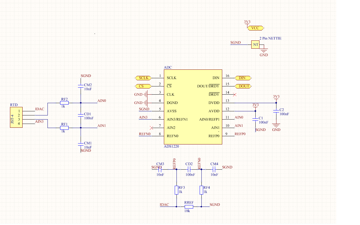
Bellow is my current ADS1220 layout:
Thanks for your help!
Regards,
Christian
