This thread has been locked.

If you have a related question, please click the "Ask a related question" button in the top right corner. The newly created question will be automatically linked to this question.

DAC39RF10: Signal output error with standalone

Part Number: DAC39RF10

Tool/software:

Hello,

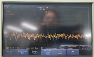
My customer is testing the signal output of the DAC39RF10 device alone on a board they designed.

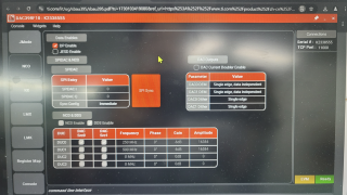
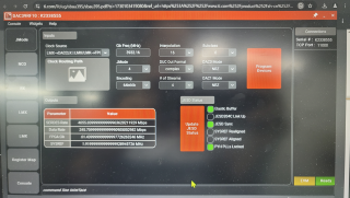
They used the settings below, which were confirmed to be output normally in standalone mode on DAC39RF10EVM.

dac39rf10-raw data.log
Fullscreen
1
2
3
4
5
6
7
8
9
10
11
12
13
14
15
16
17
18
19
DAC39RF10.read(0x02E8) # = 0x00
DAC39RF10.write(0x0000,0x80)
time.sleep(0.1)
DAC39RF10.write(0x0101,0x04)
DAC39RF10.write(0x0102,0x04)
DAC39RF10.write(0x0103,0x13)
DAC39RF10.write(0x0108,0x10)
DAC39RF10.write(0x0109,0x21)
DAC39RF10.write(0x010A,0x01)
DAC39RF10.write(0x010B,0x01)
DAC39RF10.write(0x0103,0x13)
DAC39RF10.write(0x0103,0x11)
DAC39RF10.write(0x01C2,0x01)
DAC39RF10.write(0x02E1,0x07)
DAC39RF10.write(0x02E3,0x01)
DAC39RF10.write(0x02E4,0x11)
DAC39RF10.write(0x02E8,0x00)
DAC39RF10.write(0x0723,0x1F)
DAC39RF10.write(0x0724,0x0F)
XXXXXXXXXXXXXXXXXXXXXXXXXXXXXXXXXXXXXXXXXXXXXXXXXX

Q1. Please advise on the cause of this issue and how to resolve it.

Q2. Is SYSREF clock required even when checking output on device with standalone?

Q3. Please review the customer design below to see if there are any problems.

DAC39RF10ACK-1.pdfDAC39RF10ACK-2.pdf

Thank you.

JH

  • JH,

    You didn't tell us what the issue they are seeing is so we can't comment on a possible root cause.

    Regards,

    Geoff

  • Hello Geoff,

    Thank you for your reply.

    The title of the above post is the issue. My customer tried to output a signal from the device alone with the above settings, but failed. Please answer the questions above.

    Regards,

    JH

  • Hi Geoff,

    For additional information, the DAC39RF10 chipset's Device CLK 3.932GHz and SYSREF CLK 1.92MHz are being input normally, 
    but the dac output is still not output. Please check.

    Thanks.
    KB
  • Hi KB,

    This has been assigned to the engineer in charge of this part.  He will be in touch in a few days.

    Regards,

    Geoff

  • Hey KB, 

    SYSREF is only required for certain use cases (SUBCLASS 1 operation as well as NCO synchronization if register NCO_SYNC_SRC is 1 or 2). 

    Its difficult to know what could be going wrong just from a register dump. Could you provide what clock frequency they are providing the DAC (Fdac)? In addition I think its easiest to first try to get an output in DDS mode as this doesn't require the JESD interface. 

    Below is a sequence I used to get a 2.2GHz tone with a 10GHz clock in DDS mode. This doesn't require any input from the FPGA as the device uses the internal NCO's as a tone source. Could you have them try this? The output should be a single tone at 2.2GHz*(Fdac/10E9Hz)This way we can confirm their output stage is working. 

    DAC39RF10.write[0x2e0, 0x0] # Ensure datapath is low
    DAC39RF10.write[0x100, 0x0] # JESD_EN = 0
    DAC39RF10.write[0x102, 0x2] # Set JESD_M to 2 (implying single DUC enabled)
    DAC39RF10.write[0x300, 0x2] # Set DDS_EN (NCO_EN still 0)
    DAC39RF10.write[0x321, 0x52] # Program FREQ word of DUC0 NCO
    DAC39RF10.write[0x322, 0xb8] # Program FREQ word of DUC0 NCO
    DAC39RF10.write[0x323, 0x1e] # Program FREQ word of DUC0 NCO
    DAC39RF10.write[0x324, 0x85] # Program FREQ word of DUC0 NCO
    DAC39RF10.write[0x325, 0xeb] # Program FREQ word of DUC0 NCO
    DAC39RF10.write[0x326, 0x51] # Program FREQ word of DUC0 NCO
    DAC39RF10.write[0x327, 0x38] # Program FREQ word of DUC0 NCO
    DAC39RF10.write[0x318, 0xff] # Program AMP level of DUC0 NCO (max value 0dB)
    DAC39RF10.write[0x319, 0x7f] # Program AMP level of DUC0 NCO (max value 0dB)
    DAC39RF10.write[0x304, 0x0] # ensure SPI SYNC is low
    DAC39RF10.write[0x304, 0x1] # ensure SPI SYNC is high (high edge used for sync)
    DAC39RF10.write[0x304, 0x0] # ensure SPI SYNC is low
    DAC39RF10.write[0x2e4, 0x11] # Map DUC0 to both DACA and DACB. Can also set to 0x01 to only use DACA and 0x10 to only use DACB
    DAC39RF10.write[0x2e2, 0x0] # Set DUC_GAIN to 0dB on all DUCS as only single DUC being used
    DAC39RF10.write[0x2e0, 0x1] # Enable Datapath to get output
    Note this is for NRZ output mode (default mode).

    Regards, 

    Matt

  • Hi Matt

    Thank you for your reply.
    The Fdac frequency is 3.932.16GHz.

    Regarding DDS Mode, we will inform you of the results after testing on the EVM board and Target board.

    Regards,
    KB
  • Hi Matt

    Attached are the results measured in DDS Mode with the EVM board, showing that it operates correctly.

    However, our own board still does not produce any output.

    The attached register values are those written to the target board, and they are values that work correctly on the EVM board.

    Please check if there is any issue with the input sequence or if other setting values might be incorrect.

    Regards,

    KB

    DAC39RF10_DDS_2ND.log
    Fullscreen
    1
    2
    3
    4
    5
    6
    7
    8
    9
    10
    11
    12
    13
    14
    15
    16
    17
    18
    19
    DAC39RF10.write(0x0000,0x80)
    time.sleep(0.1)
    DAC39RF10.write(0x0101,0x04)
    DAC39RF10.write(0x0102,0x04)
    DAC39RF10.write(0x0103,0x13)
    DAC39RF10.write(0x0108,0x10)
    DAC39RF10.write(0x0109,0x21)
    DAC39RF10.write(0x010A,0x01)
    DAC39RF10.write(0x010B,0x01)
    DAC39RF10.write(0x0103,0x13)
    DAC39RF10.write(0x0103,0x11)
    DAC39RF10.write(0x01C2,0x01)
    DAC39RF10.write(0x02E1,0x07)
    DAC39RF10.write(0x02E3,0x01)
    DAC39RF10.write(0x02E4,0x11)
    DAC39RF10.write(0x02E8,0x00)
    DAC39RF10.write(0x0723,0x1F)
    DAC39RF10.write(0x0724,0x0F)
    DAC39RF10.write(0x0725,0x1F)
    XXXXXXXXXXXXXXXXXXXXXXXXXXXXXXXXXXXXXXXXXXXXXXXXXX

  • Hi KB,

    Since the sequence works on the EVM, then it should work on your board as well.  Have you tried saving the config of the EVM off to a file, restarting the GUI and reloading the sequence to the EVM?  If that works, then you need to look at your custom board to see if

    1) the SPI transactions are getting to the DUT

    2) the clock is at the DUT

    3) All power rails are good at the DUT and steady during device operation

    Regards,

    Geoff

  • u tried saving the config of the EVM off to a file, restarting

    Hi all

    I have resolved the issue mentioned above.

    The cause of the problem was a cold solder joint found in the BALUN component.

    If I have any further questions during additional development,

    I will be sure to ask.

    Thank you for your assistance.

    Regards,

    KB