This thread has been locked.

If you have a related question, please click the "Ask a related question" button in the top right corner. The newly created question will be automatically linked to this question.

ADS8698: SPI communication and CLK timing, getting same Non Zero value from ADC even if input AIN is connected or not

Part Number: ADS8698
Other Parts Discussed in Thread: ADS8688

Tool/software:

Hope you guys are doing well

I would like to ask about some help, I needed to make data acquisition with ADS8698 and since I am very new to SPI I don't understand what exactly I am doing wrong
please help with this.

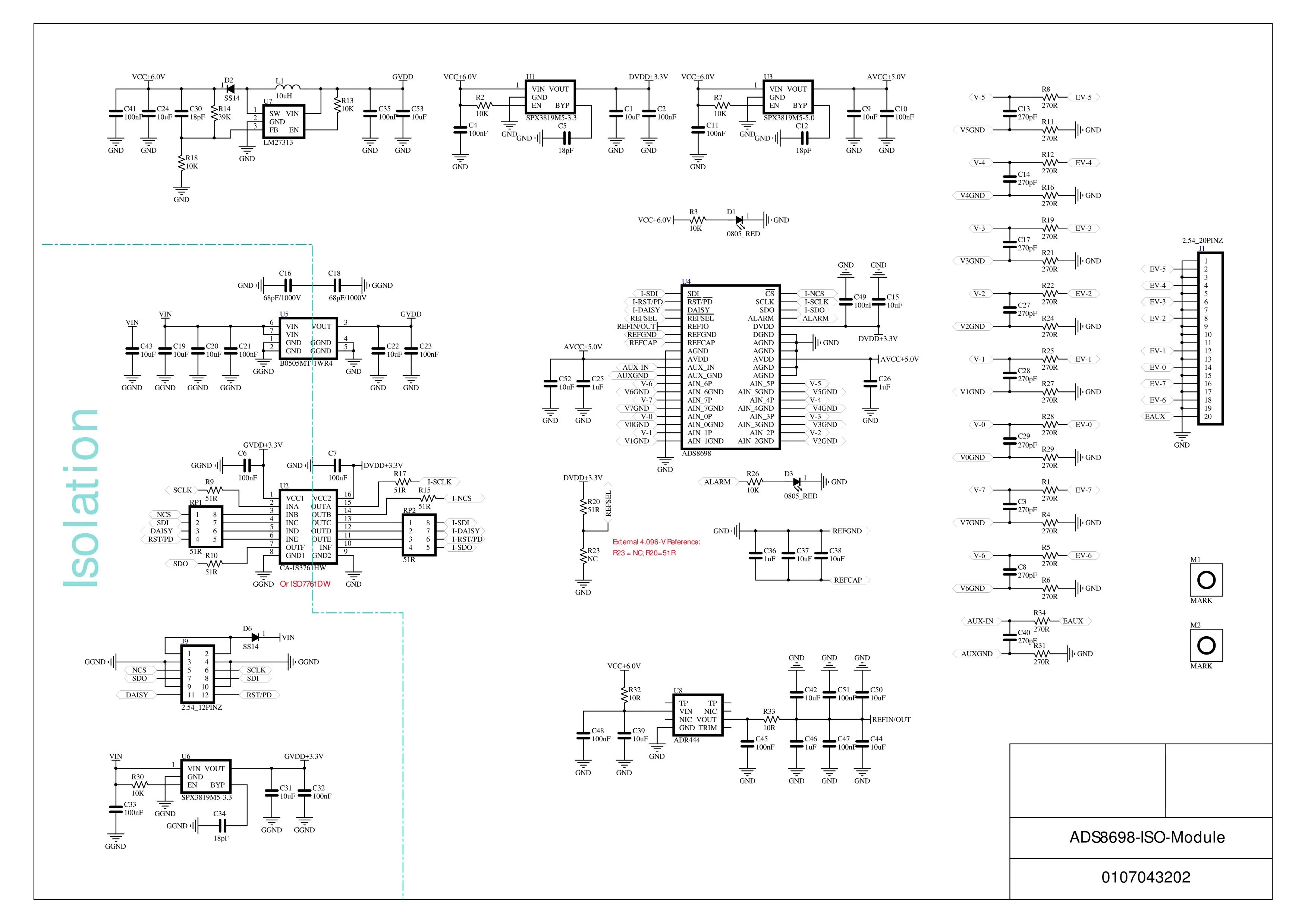
I have following board with ADS8698
https://www.aliexpress.com/item/1005006570383341.html
ADS8698 datasheet
https://www.ti.com/lit/ds/symlink/ads8698.pdf?ts=1730097926835&ref_url=https%253A%252F%252Fwww.ti.com%252Fproduct%252FADS8698 

I am connected SPI pins and Potentiometer to V on Raspi 5V and GND on Raspi GND and Middle pint to AIN0
Board VIN => 5V raspi
Board GND => GND raspi

following is my code and thing is that I am getting same value from adc if I connect input to AIN0 or not and even if I just read response just after RST command I still get same value when I print adc_val = 255

Also is it correct that I need to convert adc value to voltage as following?

adc_val * 10.24 / (2 ** 18)
# config.py ---------------------------------------------------------------
import time
import RPi.GPIO as GPIO
import spidev

RST_PIN = 25
CS_PIN = 8


SPI = spidev.SpiDev()
SPI.open(0, 0)


def digital_write(pin, value):
    GPIO.output(pin, value)

def delay_ns(ns):
    time.sleep(ns * 1e-9)

def spi_writebyte(data):
    SPI.writebytes(data)
   
def spi_readbytes(reg):
    return SPI.readbytes(reg)
   
def module_init():
    GPIO.setmode(GPIO.BCM)
    print(1)
    GPIO.setwarnings(False)
    print(2)
    GPIO.setup(RST_PIN, GPIO.OUT)
    print(3)
    GPIO.setup(CS_PIN, GPIO.OUT)
    SPI.max_speed_hz = 18_000_000 #18MHz
    SPI.mode = 1
    return 0

# End Config
# ads.py ---------------------------------------------------------------

import config
import RPi.GPIO as GPIO


CMD_REG = {
    'NO_OP'    : 0x0000, # Continue operation in previous mode
    'STDBY'    : 0x8200, # Device is placed into standby mode
    'PWR_DN'   : 0x8300, # Device is powered down
    'RST'      : 0x8500, # Program register is reset to default
    'AUTO_RST' : 0xA000, # Auto mode enabled following a reset
    'MAN_Ch_0' : 0xC000, # Channel 0 input is selected
    'MAN_Ch_1' : 0xC400, # Channel 1 input is selected
    'MAN_Ch_2' : 0xC800, # Channel 2 input is selected
    'MAN_Ch_3' : 0xCC00, # Channel 3 input is selected
    'MAN_Ch_4' : 0xD000, # Channel 4 input is selected
    'MAN_Ch_5' : 0xD400, # Channel 5 input is selected
    'MAN_Ch_6' : 0xD800, # Channel 6 input is selected
    'MAN_Ch_7' : 0xDC00, # Channel 7 input is selected
    'MAN_AUX'  : 0xE000 # AUX channel input is selected
}


rest = [ 0x85, 0x00]
class ADS:
    def __init__(self):
        self.rst_pin = config.RST_PIN
        self.cs_pin = config.CS_PIN
   
    def ADS_reset(self):
        config.digital_write(self.rst_pin, GPIO.HIGH)
        config.delay_ns(100)    
        config.digital_write(self.rst_pin, GPIO.LOW)
        config.delay_ns(100)    
        # config.spi_writebyte(rest)
        config.spi_writebyte([CMD_REG['RST']] )
        config.digital_write(self.rst_pin, GPIO.HIGH)
        # config.delay_ns(100)    

    def ADS_Write_Cmd(self, cmd_reg):
        config.digital_write(self.cs_pin, GPIO.LOW)
        config.spi_writebyte([cmd_reg] )
        config.digital_write(self.cs_pin, GPIO.HIGH)

    def ADS_Read_ADC_Data(self):
        config.digital_write(self.cs_pin, GPIO.LOW)
        config.spi_writebyte([CMD_REG['NO_OP']])
        buf = config.spi_readbytes(3)
        config.digital_write(self.cs_pin, GPIO.HIGH)
        read = (buf[0]<<16) & 0xff0000
        read |= (buf[1]<<8) & 0xff00
        read |= (buf[2]) & 0xff
        return read
   
    def ADS_init(self):
        if (config.module_init() != 0):
            return -1
       
        self.ADS_reset()
        return
   

# End ADS
# main.py ---------------------------------------------------------------

import ADS
import RPi.GPIO as GPIO

try:
    ADC = ADS.ADS()
    ADC.ADS_init()
    # ADC.ADS_Write_Cmd(ADS.CMD_REG['MAN_Ch_0'])
    # result = []

    while(1):
        adc_val = ADC.ADS_Read_ADC_Data()
        print("ADC = %lf        "%(adc_val * 10.24 / (2 ** 18)))
        print(adc_val )


except :
    GPIO.cleanup()
    print ("\r\nProgram end     ")
    exit()

# End Main
I would be grateful if you could explain how to do it correctly, I would like to get 150KSPS. I guess it is mostly about CLK timings?
  • Hi Ernist,

    Welcome to our e2e forum!  All good here!  Can you possibly provide a schematic that shows how you have the PCB you bought connected up to your controller?  Also, a logic analyzer or oscilloscope screen capture showing SCLK, CS, SDI and SDO would be more helpful than the code snippet you provided.

  • I have connected PCB to Raspberry Pi 4B with BCM2835. Unfortunately, I don't have logic analyzer or oscilloscope. Here is Raspi to PCB connection and url to PCB schematics.

  • The connections look OK, I'll assume you have relatively short wires.  Can you get access to a scope or logic analyzer?  This will be difficult without that resource for debugging.

  • Hi Ernist,

    Any luck with finding an o'scope or LA?

  • Hi Tom, hope you are doing well

    I got an oscilloscope now and it seems like communication and connection are correct
    and issues is only software, communication
    writing command and programs and reading channel values
    Could you please go through the code and check if I imelemented it wrongly

    You can see in main() function I am Initializing adc object then writing
    REG_AUTO_SEQ_EN, REG_CH_POWER_DOWN, CMD_AUTO_RST
    I am trying to use only channel 0
    so enableing AUTO_SEQ_EN for channel 0 only then powering down other channels
    and tried to to read value of channel 0 and other channels as well
    expected 3.30v for channel 0 and 0.0v or low floating values on other channels

    also, on read_channel command I am getting 5 bytes back and data in last 3 bytes
    I still do not fully understand in that order I need to write to registers programs and commands to start getting right values on channel

    Following is image of Blue - MISO and Green - SCLK


    This is the code I am using, (I' ll paste code below if code block is not loading)


    ____________ Full code ____________________
    import time
    
    import RPi.GPIO as GPIO
    import spidev
    import numpy as np
    
    
    class ADS8698:
        # Command Register Values
        CMD_NO_OP = 0x0000
        CMD_STDBY = 0x8200
        CMD_PWR_DOWN = 0x8300
        CMD_RST = 0x8500
        CMD_AUTO_RST = 0xA000
        CMD_MAN_CH0 = 0xC000
        CMD_MAN_CH1 = 0xC400
        CMD_MAN_CH2 = 0xC800
        CMD_MAN_CH3 = 0xCC00
        CMD_MAN_CH4 = 0xD000
        CMD_MAN_CH5 = 0xD400
        CMD_MAN_CH6 = 0xD800
        CMD_MAN_CH7 = 0xDC00
        CMD_MAN_AUX = 0xE000
    
        # Program Register Addresses
        REG_AUTO_SEQ_EN = 0x01
        REG_CH_POWER_DOWN = 0x02
        REG_FEATURE_SELECT = 0x03
        REG_CH0_RANGE = 0x05
        REG_CH1_RANGE = 0x06
        REG_CH2_RANGE = 0x07
        REG_CH3_RANGE = 0x08
        REG_CH4_RANGE = 0x09
        REG_CH5_RANGE = 0x0A
        REG_CH6_RANGE = 0x0B
        REG_CH7_RANGE = 0x0C
    
        # Input Range Values
        RANGE_PM_10V = 0x00    # ±10.24V  (±2.5 × VREF)
        RANGE_PM_5V = 0x01     # ±5.12V   (±1.25 × VREF)
        RANGE_PM_2_5V = 0x02   # ±2.56V   (±0.625 × VREF)
        RANGE_0_10V = 0x05     # 0 to 10.24V (2.5 × VREF)
        RANGE_0_5V = 0x06      # 0 to 5.12V  (1.25 × VREF)
    
        def __init__(self, spi_bus=0, spi_device=0, cs_pin=8, rst_pd_pin=25, ref_sel_pin=4):
            """Initialize ADS8698"""
            self.spi = spidev.SpiDev()
            self.spi.open(spi_bus, spi_device)
            self.spi.max_speed_hz = 18000000  # 18MHz
            self.spi.mode = 1
            self.spi.bits_per_word = 8
    
            self.cs_pin = cs_pin
            self.rst_pd_pin = rst_pd_pin
            self.ref_sel_pin = ref_sel_pin
    
            # Initialize GPIO
            GPIO.setmode(GPIO.BCM)
            GPIO.setup(self.cs_pin, GPIO.OUT)
            GPIO.setup(self.rst_pd_pin, GPIO.OUT)
            GPIO.setup(self.ref_sel_pin, GPIO.OUT)
    
            # Initialize the device
            self.reset()
            self.select_internal_reference()
    
        def reset(self):
            """Reset the device"""
            GPIO.output(self.rst_pd_pin, GPIO.LOW)
            time.sleep(0.001)  # 1ms
            GPIO.output(self.rst_pd_pin, GPIO.HIGH)
            time.sleep(0.010)  # 10ms
    
        def select_internal_reference(self):
            """Select internal reference"""
            GPIO.output(self.ref_sel_pin, GPIO.LOW)
            time.sleep(0.015)  # 15ms for reference to settle
    
        def write_command(self, command):
            """Write to command register"""
            GPIO.output(self.cs_pin, GPIO.LOW)
            self.spi.xfer2([(command >> 8) & 0xFF, command & 0xFF])
            GPIO.output(self.cs_pin, GPIO.HIGH)
    
        def write_program_reg(self, reg_addr, data):
            """Write to program register"""
            GPIO.output(self.cs_pin, GPIO.LOW)
            self.spi.xfer2([(reg_addr << 1) | 0x01, data, 0x00])
            GPIO.output(self.cs_pin, GPIO.HIGH)
    
        def read_program_reg(self, reg_addr):
            """Read from program register"""
            GPIO.output(self.cs_pin, GPIO.LOW)
            result = self.spi.xfer2([(reg_addr << 1) & 0xFE, 0x00, 0x00])
            GPIO.output(self.cs_pin, GPIO.HIGH)
            return result[2]
    
        def set_channel_range(self, channel, range_val):
            """Configure input range for a channel"""
            if channel > 7:
                return
            reg_addr = self.REG_CH0_RANGE + channel
            self.write_program_reg(reg_addr, range_val)
    
        def read_channel(self, channel):
            """Read conversion data from a channel"""
            channel_cmd = self.CMD_MAN_CH0 + (channel * 0x400)
            GPIO.output(self.cs_pin, GPIO.LOW)
            result = self.spi.xfer2([(channel_cmd >> 8) & 0xFF, 
                                    channel_cmd & 0xFF,
                                    0x00, 0x00, 0x00])
            GPIO.output(self.cs_pin, GPIO.HIGH)
            
            value = ((result[2] << 16) | (result[3] << 8) | result[4]) & 0x3FFFF
            print(f"CHANNEL {channel}")
            print(f"Response to read_channel {result}")
            return value
    
        def configure_auto_sequence(self, channel_mask):
            """Configure auto-sequence mode"""
            self.write_program_reg(self.REG_AUTO_SEQ_EN, channel_mask)
    
        def channel_pw_dn(self, channel_mask):
            """Powers down channels"""
            self.write_program_reg(self.REG_CH_POWER_DOWN, channel_mask)
    
        def start_auto_sequencing(self):
            """Start the auto-sequencing mode with current configuration"""
            self.write_command(self.CMD_AUTO_RST)
        
        def read_auto_sequence(self):
            """Read conversion data in auto sequence mode"""
            GPIO.output(self.cs_pin, GPIO.LOW)
            result = self.spi.xfer2([(self.CMD_NO_OP >> 8) & 0xFF,
                                    self.CMD_NO_OP & 0xFF,
                                    0x00, 0x00, 0x00])
            GPIO.output(self.cs_pin, GPIO.HIGH)
            
            value = ((result[2] << 16) | (result[3] << 8) | result[4]) & 0x3FFFF
            return value
        
    
        def convert_to_voltage(self, adc_value, range_val):
            """Convert ADC value to voltage"""
            vref = 4.096  # Internal reference voltage
            
            if range_val == self.RANGE_PM_10V:
                return ((adc_value / 262144.0) - 0.5) * (4 * vref)
            elif range_val == self.RANGE_PM_5V:
                return ((adc_value / 262144.0) - 0.5) * (2 * vref)
            elif range_val == self.RANGE_PM_2_5V:
                return ((adc_value / 262144.0) - 0.5) * vref
            elif range_val == self.RANGE_0_10V:
                return (adc_value / 262144.0) * (2 * vref)
            elif range_val == self.RANGE_0_5V:
                return (adc_value / 262144.0) * vref
            else:
                return 0
    
        def cleanup(self):
            """Cleanup GPIO and SPI"""
            self.spi.close()
            GPIO.cleanup()
    
    try:
        adc = ADS8698()
        adc.configure_auto_sequence(0x01)
        adc.channel_pw_dn(0b11111110)
        adc.start_auto_sequencing()
    
        for i in range(8):
            adc.set_channel_range(i, ADS8698.RANGE_0_5V)  
        
        # while(1):
        for i in range(8):
            # i = 0
            adc_val = adc.read_channel(i)
            print(f"Channel: {i}, Voltage: {adc.convert_to_voltage(adc_val, ADS8698.RANGE_0_5V)}")
            print("----------------------------------------------")
            # time.sleep(1)
    except KeyboardInterrupt:
            print("\nStopping data acquisition...")
    finally:
        adc.cleanup()


    and this is the outputs I am getting
    _______________ output for all channels ______________________
    
    CHANNEL 0
    Response to read_channel [0, 0, 255, 255, 255]
    Channel: 0, Voltage: 4.0959843750000005
    ----------------------------------------------
    CHANNEL 1
    Response to read_channel [0, 0, 164, 200, 191]
    Channel: 1, Voltage: 0.802984375
    ----------------------------------------------
    CHANNEL 2
    Response to read_channel [0, 0, 163, 189, 255]
    Channel: 2, Voltage: 3.831984375
    ----------------------------------------------
    CHANNEL 3
    Response to read_channel [0, 0, 159, 240, 191]
    Channel: 3, Voltage: 4.0349843750000005
    ----------------------------------------------
    CHANNEL 4
    Response to read_channel [0, 0, 156, 193, 255]
    Channel: 4, Voltage: 0.7759843750000001
    ----------------------------------------------
    CHANNEL 5
    Response to read_channel [0, 0, 153, 94, 191]
    Channel: 5, Voltage: 1.402984375
    ----------------------------------------------
    CHANNEL 6
    Response to read_channel [0, 0, 149, 225, 63]
    Channel: 6, Voltage: 1.924984375
    ----------------------------------------------
    CHANNEL 7
    Response to read_channel [0, 0, 148, 2, 127]
    Channel: 7, Voltage: 0.009984375
    ----------------------------------------------
    
    _______________ output for channels 0 (AIN0) ______________________
    CHANNEL 0
    Response to read_channel [0, 0, 255, 255, 255]
    Channel: 0, Voltage: 4.0959843750000005
    ----------------------------------------------


    ____________ Full code ____________________
    import time

    import RPi.GPIO as GPIO
    import spidev
    import numpy as np


    class ADS8698:
    # Command Register Values
    CMD_NO_OP = 0x0000
    CMD_STDBY = 0x8200
    CMD_PWR_DOWN = 0x8300
    CMD_RST = 0x8500
    CMD_AUTO_RST = 0xA000
    CMD_MAN_CH0 = 0xC000
    CMD_MAN_CH1 = 0xC400
    CMD_MAN_CH2 = 0xC800
    CMD_MAN_CH3 = 0xCC00
    CMD_MAN_CH4 = 0xD000
    CMD_MAN_CH5 = 0xD400
    CMD_MAN_CH6 = 0xD800
    CMD_MAN_CH7 = 0xDC00
    CMD_MAN_AUX = 0xE000

    # Program Register Addresses
    REG_AUTO_SEQ_EN = 0x01
    REG_CH_POWER_DOWN = 0x02
    REG_FEATURE_SELECT = 0x03
    REG_CH0_RANGE = 0x05
    REG_CH1_RANGE = 0x06
    REG_CH2_RANGE = 0x07
    REG_CH3_RANGE = 0x08
    REG_CH4_RANGE = 0x09
    REG_CH5_RANGE = 0x0A
    REG_CH6_RANGE = 0x0B
    REG_CH7_RANGE = 0x0C

    # Input Range Values
    RANGE_PM_10V = 0x00 # ±10.24V (±2.5 × VREF)
    RANGE_PM_5V = 0x01 # ±5.12V (±1.25 × VREF)
    RANGE_PM_2_5V = 0x02 # ±2.56V (±0.625 × VREF)
    RANGE_0_10V = 0x05 # 0 to 10.24V (2.5 × VREF)
    RANGE_0_5V = 0x06 # 0 to 5.12V (1.25 × VREF)

    def __init__(self, spi_bus=0, spi_device=0, cs_pin=8, rst_pd_pin=25, ref_sel_pin=4):
    """Initialize ADS8698"""
    self.spi = spidev.SpiDev()
    self.spi.open(spi_bus, spi_device)
    self.spi.max_speed_hz = 18000000 # 18MHz
    self.spi.mode = 1
    self.spi.bits_per_word = 8

    self.cs_pin = cs_pin
    self.rst_pd_pin = rst_pd_pin
    self.ref_sel_pin = ref_sel_pin

    # Initialize GPIO
    GPIO.setmode(GPIO.BCM)
    GPIO.setup(self.cs_pin, GPIO.OUT)
    GPIO.setup(self.rst_pd_pin, GPIO.OUT)
    GPIO.setup(self.ref_sel_pin, GPIO.OUT)

    # Initialize the device
    self.reset()
    self.select_internal_reference()

    def reset(self):
    """Reset the device"""
    GPIO.output(self.rst_pd_pin, GPIO.LOW)
    time.sleep(0.001) # 1ms
    GPIO.output(self.rst_pd_pin, GPIO.HIGH)
    time.sleep(0.010) # 10ms

    def select_internal_reference(self):
    """Select internal reference"""
    GPIO.output(self.ref_sel_pin, GPIO.LOW)
    time.sleep(0.015) # 15ms for reference to settle

    def write_command(self, command):
    """Write to command register"""
    GPIO.output(self.cs_pin, GPIO.LOW)
    self.spi.xfer2([(command >> 8) & 0xFF, command & 0xFF])
    GPIO.output(self.cs_pin, GPIO.HIGH)

    def write_program_reg(self, reg_addr, data):
    """Write to program register"""
    GPIO.output(self.cs_pin, GPIO.LOW)
    self.spi.xfer2([(reg_addr << 1) | 0x01, data, 0x00])
    GPIO.output(self.cs_pin, GPIO.HIGH)

    def read_program_reg(self, reg_addr):
    """Read from program register"""
    GPIO.output(self.cs_pin, GPIO.LOW)
    result = self.spi.xfer2([(reg_addr << 1) & 0xFE, 0x00, 0x00])
    GPIO.output(self.cs_pin, GPIO.HIGH)
    return result[2]

    def set_channel_range(self, channel, range_val):
    """Configure input range for a channel"""
    if channel > 7:
    return
    reg_addr = self.REG_CH0_RANGE + channel
    self.write_program_reg(reg_addr, range_val)

    def read_channel(self, channel):
    """Read conversion data from a channel"""
    channel_cmd = self.CMD_MAN_CH0 + (channel * 0x400)
    GPIO.output(self.cs_pin, GPIO.LOW)
    result = self.spi.xfer2([(channel_cmd >> 8) & 0xFF,
    channel_cmd & 0xFF,
    0x00, 0x00, 0x00])
    GPIO.output(self.cs_pin, GPIO.HIGH)

    value = ((result[2] << 16) | (result[3] << 8) | result[4]) & 0x3FFFF
    print(f"CHANNEL {channel}")
    print(f"Response to read_channel {result}")
    return value

    def configure_auto_sequence(self, channel_mask):
    """Configure auto-sequence mode"""
    self.write_program_reg(self.REG_AUTO_SEQ_EN, channel_mask)

    def channel_pw_dn(self, channel_mask):
    """Powers down channels"""
    self.write_program_reg(self.REG_CH_POWER_DOWN, channel_mask)

    def start_auto_sequencing(self):
    """Start the auto-sequencing mode with current configuration"""
    self.write_command(self.CMD_AUTO_RST)

    def read_auto_sequence(self):
    """Read conversion data in auto sequence mode"""
    GPIO.output(self.cs_pin, GPIO.LOW)
    result = self.spi.xfer2([(self.CMD_NO_OP >> 8) & 0xFF,
    self.CMD_NO_OP & 0xFF,
    0x00, 0x00, 0x00])
    GPIO.output(self.cs_pin, GPIO.HIGH)

    value = ((result[2] << 16) | (result[3] << 8) | result[4]) & 0x3FFFF
    return value

    def convert_to_voltage(self, adc_value, range_val):
    """Convert ADC value to voltage"""
    vref = 4.096 # Internal reference voltage

    if range_val == self.RANGE_PM_10V:
    return ((adc_value / 262144.0) - 0.5) * (4 * vref)
    elif range_val == self.RANGE_PM_5V:
    return ((adc_value / 262144.0) - 0.5) * (2 * vref)
    elif range_val == self.RANGE_PM_2_5V:
    return ((adc_value / 262144.0) - 0.5) * vref
    elif range_val == self.RANGE_0_10V:
    return (adc_value / 262144.0) * (2 * vref)
    elif range_val == self.RANGE_0_5V:
    return (adc_value / 262144.0) * vref
    else:
    return 0

    def cleanup(self):
    """Cleanup GPIO and SPI"""
    self.spi.close()
    GPIO.cleanup()

    try:
    adc = ADS8698()
    adc.configure_auto_sequence(0x01)
    adc.channel_pw_dn(0b11111110)
    adc.start_auto_sequencing()

    for i in range(8):
    adc.set_channel_range(i, ADS8698.RANGE_0_5V)

    # while(1):
    for i in range(8):
    # i = 0
    adc_val = adc.read_channel(i)
    print(f"Channel: {i}, Voltage: {adc.convert_to_voltage(adc_val, ADS8698.RANGE_0_5V)}")
    print("----------------------------------------------")
    # time.sleep(1)
    except KeyboardInterrupt:
    print("\nStopping data acquisition...")
    finally:
    adc.cleanup()


  • sorry, object initialization is in try not in main() function in provided code 
    I hope you can explain what I am doing wrong
    I still think I am sending bytes in wrong way or wrong bit wise operations 

    Let me know what should I test using oscilloscope 
    thank you for your help

  • Hi Ernist,

    It will take some time to go through your code.  In a few words, can you tell me what sort of input voltage you are dealing with and what your expected versus actual conversion results are?

  • Hello, Tom Sorry for late reply 

    I am passing 3.3v on channel 0 using potentiometer, and expected to get 3.3.v voltage but getting output in range of 2.1v to 2.8v and it fluctuates a lot, I was expecting constant value. And if I disconnect input on channels I am getting around 4.0v I guess it is invalid output mentioned in datasheet. 

  • Hi Ernist,

    Try shorting AIN0 to ground at J1 and see what kind of conversion results you get - it should be relatively stable at 0 with perhaps a couple LSBs toggling.

  • How is it going Ernist?  Have you made any progress?

  • Hi Tom, I recently got new ADS8688 and everything worked find with that. So just decided to stick with that. thank you for your assist. Before we close this thread I wanted to ask if there a way to get exact sampling rate? I managed to get around 150 ksps, applying delays to get close to constant periods between each samples, I guess sampling time for each sample stays same since it takes same 32 clocks each time, right? And still there is a bit of fluctuation in sampling rate which is around 0.015% which is okay but if there a way I would like to learn about it. Is it achievable just with low level hardware management using timers and interrupts? If you have source for that I would be happy if you could share. Otherwise, my issues is solved and thank you for you support/ 
    Have a good day. 

  • Hi Ernist,

    Unfortunately I don't have code for you.  The conversion time is fixed by an internal clock - the acquisition (sampling) time has a minimum value, but there is no MAX value - basically the ADS8698 goes back into acquisition mode as soon as the conversion process is complete.  If you have a good timer on your CPU, you could use that to toggle the /CS input and initiate a conversion cycle.